Building A Quadcopter For Newbie

Drones are one of the rising technologies in the world and it became very popular that we see it in news on places that have armed conflicts, aerial photography like GoPro drones and even for customer care like the Prime Air delivery system from Amazon which is designed to get packages to customers using small unmanned aerial vehicles (aka drones).

If this is the first time to read about how to build a quadcopter, then this post is for you. Boris Landoni from OpenElectronics made a detailed how-to tutorial on how to build a quadcopter in two parts.

quadcopter

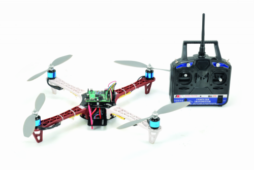
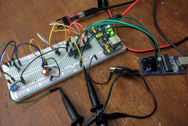
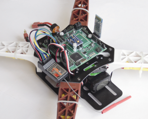
As the name implies, the quadcopter has four propellers and to control them we need a lot of electronics parts and with no doubt a control board. The control board which Boris Landoni build is based on Arduino Mega and manages the engines of the drone with up to eight outputs, receives commands from a remote controller and supports the telemetry function via smartphone using HC-05 Bluetooth module.

mainboardquad

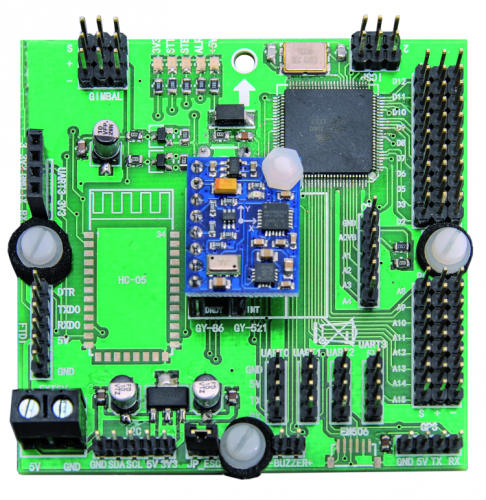
GY-86 flight control sensor module is used on top of main board (the small blue board) which combines MPU-6050 (3-axis accelerometer and 3-axis gyroscope), a digital 3-axis compass HMC5883L form Honeywell and the pressure sensor MS5611 MEAS.

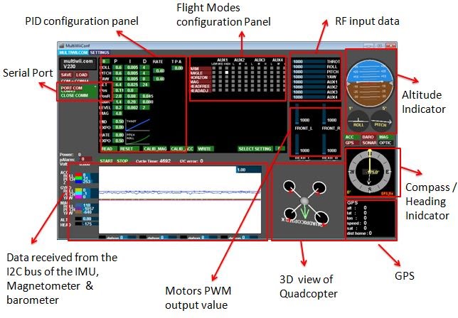
Boris talked about the firmware that could be used to control the main board, but chose MultiWii firmware which is a general purpose software to control a multirotor RC model.

MultiWii Configuration GUI - Image Source eng.ucsd.edu
MultiWii Configuration GUI – Image Source eng.ucsd.edu

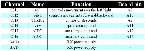
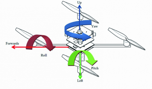
He used six-channel remote control operating on the 2.4 Ghz frequency. Each channel controls one surface or component in the quadcopter.

tablercchannels

flightglossary

 Main Board Assembled on the Frame and Connected with RC Receiver (the black box in the left of the main board)
Main Board Assembled on the Frame and Connected with RC Receiver (the black box in the left of the main board)

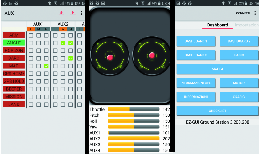
You can do both the telemetry and the control via Bluetooth from your smartphone using EZ-GUI Android application, which is a Ground Control Station (GCS) for UAVs based on MultiWii and Cleanflight.

ez-gui

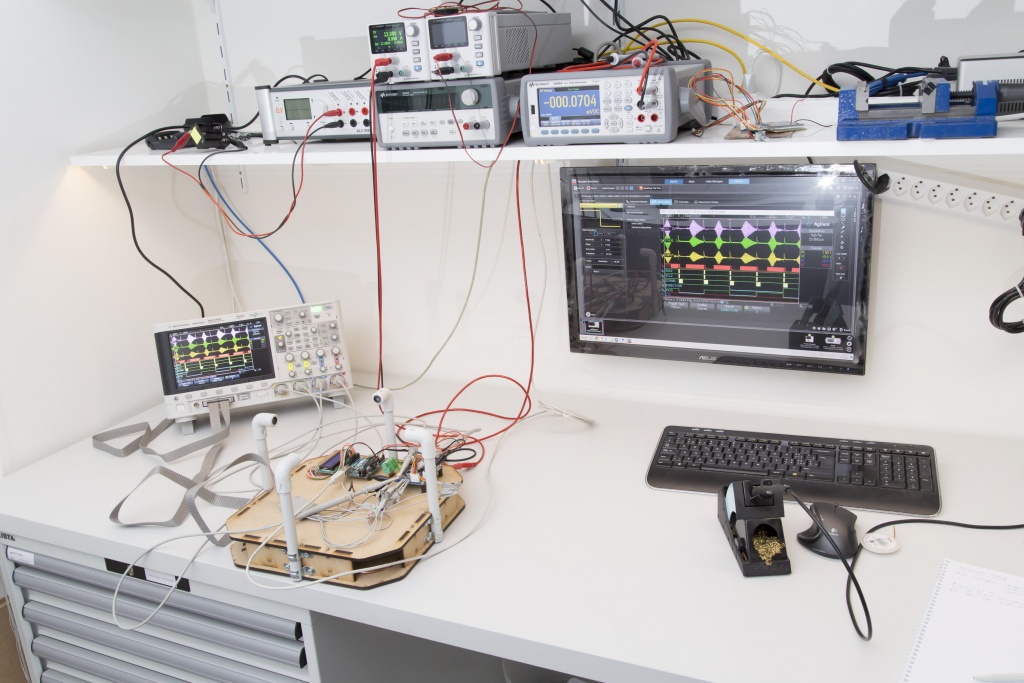
Boris talked about PID parameters calibration, a control loop feedback mechanism used to control systems. He shared an interesting video showing how changing these values changes the behavior of the quadcopter.


The full assembly instructions and other important notes by Boris are found in the two part how-to tutorial: Part1Part2.

Bill of Material
Bill of Material

Introduction to I²C and SPI protocols

figure1

byteparadigm.com has a nice introductory article on I2C and SPI protocols:

Today, at the low end of the communication protocols, we find I²C (for ‘Inter-Integrated Circuit’, protocol) and SPI (for ‘Serial Peripheral Interface’). Both protocols are well-suited for communications between integrated circuits, for slow communication with on-board peripherals. At the roots of these two popular protocols we find two major companies – Philips for I²C and Motorola for SPI – and two different histories about why, when and how the protocols were created.

Introduction to I²C and SPI protocols – [Link]

Benefits of Using A Buck-Boost Converter As A Pre-regulator For LDOs

Intersil published a new white paper titled “Preventing Subsystem Brownouts in Mobile Devices“. This white paper demonstrates the benefit of using a buck-boost converter as a pre-regulator, which leads to better overall system efficiency and enhanced battery life.

preldobuckboost

Systems powered from a battery may have voltage brownout when they are subjected to a burst current discharge, that is because of internal resistance of the battery. The internal resistance in Li-Ion battery varies according to its charging level. It can reach 200 Milli-ohm at the end of the discharge. Thus, a 4A burst current can cause an 800mV droop at the terminal, pushing the nominal 3.4V voltage to 2.6V, which is considered as a brownout voltage if the target LDO output is 2.85V. In this case boost converters prevent the momentary brownout.

Overall system efficiency is another useful aspect of using a buck-boost converter as a pre-regulator. The battery voltage is first converted to a voltage slightly higher than the highest LDO output voltage of the target LDOs, which is typically 3.3V. The buck-boost output is then set to 3.4V. So, the LDOs see a 3.4V input voltage, regardless of the battery voltage.

We can see, by numbers, the improvement of efficiency by comparing the two setups, with and without using the buck-boost converter.

nonpreldobuckboosteff

preldobuckboosteff

The figure below shows the comparison of battery discharge with and without a pre-regulator, while running the same applications with the same battery. You can see 12% enhancement to battery life.

runtimepreregbb

[White Paper]

Intersil’s Switching Regulators Adopted in Huawei P9 Smartphone

isl91110-huawei-medium

Intersil announces the adoption of its latest family of buck-boost switching regulators in one of Huawei’s newest smartphone. The ISL91110 buck-boost switching regulator powers the Huawei P9 smartphone’s key system peripherals providing excellent efficiency and performance. [via]

Intersil’s ISL91110 buck-boost switching regulator supplies power to key system peripherals in the P9 dual-camera smartphone, using a proprietary, fully synchronous four-switch architecture. This advanced architecture enables the seamless transition from buck to boost and delivery of up to 2.5A output current at the lowest single-cell Li-ion battery voltages to extend battery life.

We previously covered a member of this family. Check it here: ISL91128 – A New Buck-Boost Regulator With I2C Interface From Intersil

Intersil’s Switching Regulators Adopted in Huawei P9 Smartphone – [Link]

Adding ADC to Microcontrollers without ADC

testrig-1-640x428

@ swharden.com show us how to interface an analog signal to a microcontroller that doesn’t have an ADC.

I recently had the need to carefully measure a voltage with a microcontroller which lacks an analog-to-digital converter (ADC), and I hacked together a quick and dirty method to do just this using a comparator, two transistors, and a few passives. The purpose of this project is to make a crystal oven controller at absolute minimal cost with minimal complexity. Absolute voltage accuracy is not of high concern (i.e., holding temperature to 50.00 C) but precision is the primary goal (i.e., hold it within 0.01 C of an arbitrary target I set somewhere around 50 C).

Adding ADC to Microcontrollers without ADC – [Link]

Analog front-end IC linearizes sensors

160908edne-linear2986

Susan Nordyk @ edn.com discuss about LTC2986 which is able to digitize and linearize a combination of temperature sensors in Celsius or Fahrenheit degrees.

A 10-channel temperature-measurement IC, the LTC2986 from Linear Technology directly digitizes any combination of thermocouples, RTDs, thermistors, and external diodes with 0.1°C accuracy and 0.001°C resolution. The analog front-end device combines three 24-bit delta-sigma ADCs with all the necessary excitation and control circuits for each sensor. On-chip EEPROM stores user configuration data and custom sensor coefficients, eliminating IC or sensor programming by a host processor.

The LTC2986 measures absolute microvolt-level signals from thermocouples and ratiometric resistance from RTDs and thermistors. It performs linearization and outputs the results in °C or °F. With 10 analog inputs, the LTC2986 accommodates up to 9 thermocouples, 4 RTDs, 4 thermistors, and/or 10 diodes, with support for Type B, E, J, K, N, S, R, and T thermocouples; 2-wire, 3-wire, and 4-wire RTDs; and 2.25-kΩ to 30-kΩ thermistors.

Analog front-end IC linearizes sensors – [Link]

MPPT Solar Charger Design based on PIC18F26J50

solarchargereagletop-768x541

At the core of the design is a PIC18F26J50 in a 28 pin SOIC package. It’s capable of running at down to 2.15 volts and consumes extremely little power when running at lower clock speeds. And apart from that it features USB so we can have all the benefits of USB without any external components except, of course, a USB socket.

MPPT Solar Charger Design based on  [Link]

CO2, temperature and humidity monitor

pic-front-panel3-600

An open source CO2 monitoring project from Roving Dynamics:

The project described below uses a MH-Z16 or MH-Z19 CO2 sensor and a DHT-22 (or DHT-11 if less accuracy is required) to measure the Temperature and Humidity. It has a 4 line by 20 character LCD Display to show the current readings and status, a warning alarm and two relays which can be triggered on a low CO2 (Generally above 1000 ppm) normally to switch on an extractor fan and a high level (4000 ppm) which will trigger a warning device such as an external alarm. There are two models I used the 0 to 5000 ppm device here but the code will be the same for the 0 to 10000 ppm model

CO2, temperature and humidity monitor – [Link]

Ultrasonic Anemometer Project Progress

20160907_standaloneanemometer_029

In the mean time I managed to do some rudimentary testing and now feel confident to take orders. These tests concern the hardware only. What I said last time about the state of the software still applies. But let me tell you what I’ve been able to test so far.

Ultrasonic Anemometer Project Progress – [Link]

8 Channel Optically Isolated IO Board

8-channel-optically-isolated-io-board-c047_w

Opto-Isolated I/O Board offers a compact & convenient way to interface industrial type inputs/outputs to your microcontroller boards, Signal transmission between circuits of different potentials and impedances etc.

Specifications

  • 4 opto-isolated inputs & 4 opto-isolated outputs
  • Std TTL input signals for opto-couplers
  • Interfacing is via 10-pin Box Header and Screw terminal type connector
  • Power source LED indicator
  • Four mounting holes 3.2 mm each
  • PCB dimensions 54 mm x 64 mm

8 Channel Optically Isolated IO Board – [Link]

TOP PCB Companies