In this video educ8s.tv shows us how to build an Arduino Robot that can avoid obstacles:
The robot that we are going to build today is moving around and it can detect obstacles and avoid them. It uses a supersonic distance sensor in order to measure the distance from its front side. When it detects and obstacle it stops, goes backward for a few cms, looks around and then it turns to the direction with the more space available. As you are going to find out, building this impressive little robot is extremely easy and fun. It will not take you more than a couple of hours from start to finish. Then you can use my code, modify it and implement your own robot behavior easily. It is a great learning experience and great introduction to robotics for kids and adults. Let’s build it!
A DIY obstacle avoiding robot using an SG90 servo and Ultrasonic Sensor – [Link]
Maxim presents its Cell-String Optimizer as the first IC to perform MPPT (maximum power point tracking) at low level in a panel; it allows photovoltaic (PV) panels to harvest significantly more energy and simplifies design complexity for solar installation projects. by Graham Prophet @ edn-europe.com
Maxim’s cell-string optimizers are highly integrated DC-DC converters that replace the bypass diode and perform maximum power point tracking (MPPT) deep inside the PV module. By replacing each diode with a MPPT device, the on-off response to performance mismatch is eliminated; every cell-string contributes maximum power without interfering with the power production capability of others. This enhanced degree of flexibility leads to increased energy production; eliminating collateral performance loss due to module mismatch, degradation, soiling, localized shading, and row shading loss mechanisms.
PV cell string optimizer boosts solar panel output up to 30% – [Link]
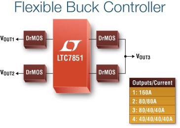
The LTC7851 is a quad output multiphase synchronous step-down DC/DC controller with accurate current sharing between phases and differential output voltage sensing. This controller works in conjunction with external power train devices such as DrMOS and power blocks as well as discrete N-channel MOSFETs and associated gate drivers, enabling flexible design configurations. Up to 8 phases with two ICs can be paralleled and can be clocked out-of-phase to minimize input and output filtering for very high current requirements up to 260A. It operates with a VCC supply voltage from 3V to 5.5V, is designed for step-down conversion from an input voltage from 3V to 27V and produces one to four independent output voltages ranging from 0.6V to 5V. The device’s voltage mode control architecture allows for a selectable fixed operating frequency from 250kHz to 2.25MHz or it can be synchronized to an external clock over the same range. Applications include power distribution and industrial systems, FPGA, DSP, processor and ASIC supplies.
LTC7851 – Quad Output, Multiphase Step-Down Voltage Mode DC/DC Controller with Accurate Current Sharing – [Link]
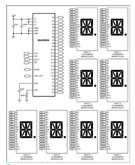
App note from Maxim on using the MAX6954 to drive 14-segment monocolor LEDs, (PDF):
This article is how-to guide, intended as a quick learning aid for engineers considering using the MAX6954 to drive 14-segment monocolor LEDs.
The MAX6954 is a versatile display driver, capable of controlling a mix of discrete, 7-segment, 14-segment, and 16-segment LED displays through a serial interface. This application note shows a typical application and configuration for driving eight mono-color, 14-segment LEDs.
See the MAX6954 data sheet for additional information about MAX6954 features.
Driving 14-segment displays with the MAX6954 – [Link]
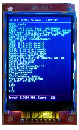
As it happens I’m experimenting on a 1284 chip which while being Arduino-compatible kind of, it does have another serial port, so without disconnecting my FTDI – I hooked up the second serial port to the home control serial and fired the DEBUG command at the latter.
As you can see on the left, a perfectly usable terminal. At this point despite YEARS of VT-100 wilderness I’d mastered the colours and scrolling area controls – thanks to this handy VT-100-related link. Not all of the commands work and in order to make a character counter I had to do a custom colour save.”
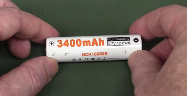
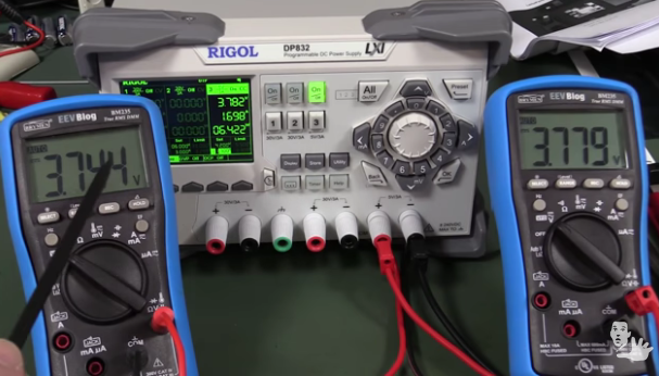
David Jones has another useful video tutorial about how to safely charge Lithium Ion and Lithium Polymer batteries with a bench power supply. The purpose of this tutorial is to learn how to use your lab power supply to charge your Lithium Ion battery when you don’t have a special charger circuit to do so.
He used NCR18650B in his tutorial, a 3.6V 3400mAh Lithium Ion battery from Panasonic.
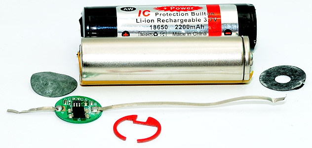
David warned us that charging this type of battery is quite dangerous if we didn’t do it in the correct way. Even with the presence of protection circuit in Lithium Ion battery.
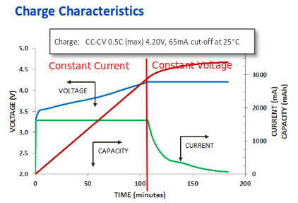
You can find the charging diagram in NCR18650B battery datasheet.
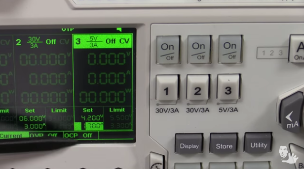
According to the datasheet, the charging current is 1625mA and the charging voltage is 4.2V. Charging consists of two stages, first one is the constant current stage where you must supply a 1625mA constant current and when the battery voltage reaches 4.20V, the second stage starts, which is the constant voltage stage. In this stage, the current will naturally drop down, and the cutoff is typically about 10% of charging current so it’s about 170mA.
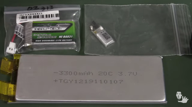
This tutorial applies to all Lithium Ion and Lithium Polymer batteries not only NCR18650B.
You can perform this 2-stage charging using your power supply, but it must supports CC(Constant Current) and CV(Constant Voltage) modes. You can read the following Q&A in electronics.stackexchange to learn what constant current and voltage modes mean. You can build a power supply with CC and CV modes for yourself if you don’t have a budget to buy a ready made one.
David’s Power Supply Setting With 4.2V CV and 1700mA CCThe Battery Charges in The First CC Stage Sinking 1698mA
David said that using this type of float charging/trickle charging is not recommended, because it will build-up or plate the metallic parts inside the battery. So It’s better to use dedicated ICs designed for the float charging.
David mentioned in his video that a complete tutorial is available for whom who want to know in details how to charge lithium ion battery.
Welcome to the second post of the “Exploring Eagle CAD ULPs” series. Every week we will publish a new post about one useful ULP in Eagle CAD.
“ULP” User Language Program is a plain text file which is written in a C-like syntax and can be used to access the EAGLE data structures and to create a wide variety of output files. You can consider it like a plug-in for Eagle.
You can reach the posts published in this series using the following link.
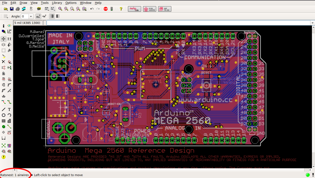
In this post we will discover “Unrouted.ULP” by Daniel Mack. The job of this ULP is to zoom to the first unrouted wire in the board editor. This might be helpful when searching for tiny leftover air wires especially in big boards.
When we use ‘ratsnest in layout editor, a result with remaining airwires is shown in the bottom of the editor. Sometimes airwires are not visible to our eyes and need a lot of searching.
One Airewire Is Left – See the red circle
“Unrouted.ULP” can zoom to unrouted line and solve this problem for us.
When I started to deal with Chinese electronics suppliers from websites like Alibaba, Aliexpress and Taobao, I discovered that there are huge amount of undiscovered tools from the Chinese market. They are not easily discovered, maybe due to the Chinese language barrier, especially when we deal with a Chinese website like Taobao or maybe because most of us are used to deal with known electronics distributors like Sparkfun.
I also discovered that I can get my stuff from there in a lower price and in most cases of the same quality.
We can’t deny that dealing with known and trusted electronics stores such as Sparkfun and Adafruit is more comfortable and safe, but our proposal is an alternative one.
That doesn’t mean that our series will focus only on tools from Chinese suppliers. We will also explore special tools from Ebay, Tindie and other resources.
This series is weekly, so stay tuned! Please note that when we talk about a tool from a certain store or a supplier, we don’t claim that we guarantee the quality and if the store is trustworthy.
You can reach the posts published in this series using the following link.
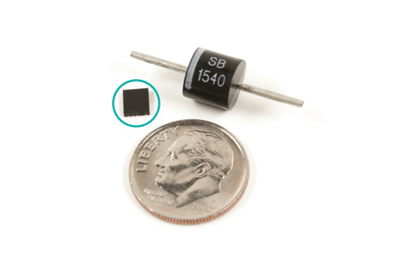
Welcome to the first post of our series “Tools for the Electronics Hobbyist”. We are going to talk about graphical components tester, which I found on “91make” store on Taobao and it seems that they’re specialists in graphical components testers.
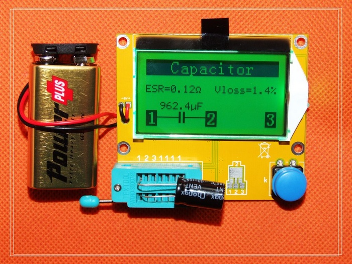
This tool is used to discover the type and main features (like value and some other electrical characteristics) of the majority of discrete components like transistors, diodes, resistors, capacitors and other components.
This is useful when you have an unknown part. As you know a part with TO-220 package can be a BJT, a MOSFET or maybe something else. It is also useful when you know the basic function of the part in your hand and you need to know some of its characteristics.
Features:
Can used with npn and pnp transistors, n-channel and p-channel mosfet, diodes (including double diodes), thyristors, transistors, resistors, capacitors and other components.
Measuring the gate threshold voltage and gate capacitance of MOSFET.
Amplification factor (gain) of the BJT and the base of the forward bias voltage.
Getting the pinout of the component.
Use 9v battery for power supply.
I found a video on Youtube for the same tool tested with a lot of components
It’s available for 40 RMB which is about 6$, and you can see that it’s cheaper than Ebay or Tindie suppliers. You can also read the Hackaday review about this tool.
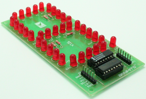
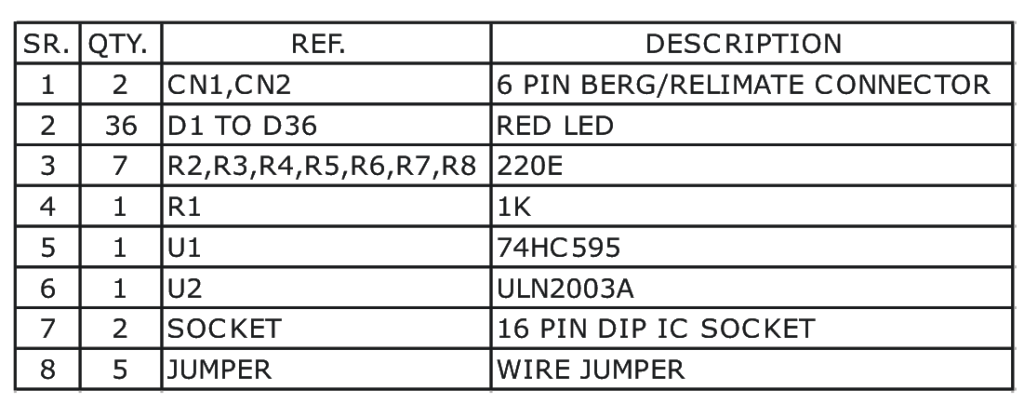
Single Digit Big Display module using 74HC595 IC project will display large size 7 segment single digit number. 3.5inch height, which can be visible over large distance. More digit can be connected serially to each other easily trough connector.
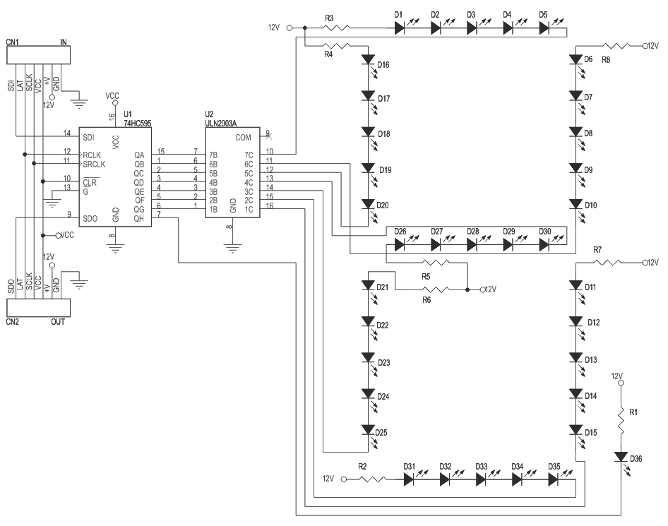
This circuit is a single digit seven segment big display using a set of 5 LEDs per segment and a shift register for easy control by micro-controller input. Each of the LEDs used in this project are 5mm high glow type.
Specifications
A ULN2003 IC helps sink higher current flowing through the LEDs to grounds.
Resistor R1 to R8 are current limiting Resistors for the LEDs connected in series.
CN1 Connector is Data In connector
CN2 Connector is optional Data Out Connector if you need to stack more than 1 single display board in series
+V CN1 & CN2 should be connected to higher voltage to drive the LEDs
VCC Should be connected to 5V DC. This supply can be source from host controller
Each Segment made up of 5LEDs
Series Current limiting resistor provide on each segment
Series latched type display using SPI protocol
Separate Header Connecter for connection input/output