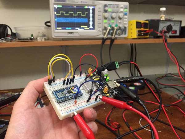
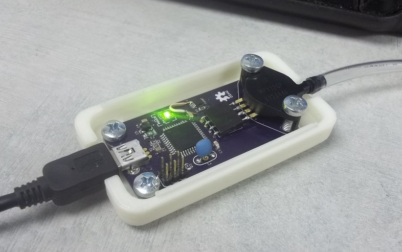
Today I made a high frequency multiplier using a single component: the ICS501 PLL clock multiplier IC. This chip provides 2x, 5x, 8x (and more) clock multiplication using an internal phased-lock loop (PLL). At less than a dollar on eBay, $1.55 on mouser, and $0.67 on Digikey, they don’t break the bank and I’m glad I have a few in my junk box! I have a 10MHz frequency standard which I want to use to measure some 1Hz (1pps) pulses with higher precision, so my general idea is to use a frequency multiplier circuit to increase the frequency (to 80 MHz) and use this to run a counter IC to measure the number of clock pulses between the PPS pulses.
Jesus @ jechavarria.com pointed us to his latest project, a portable temp, humidity and ambient light datalogger.
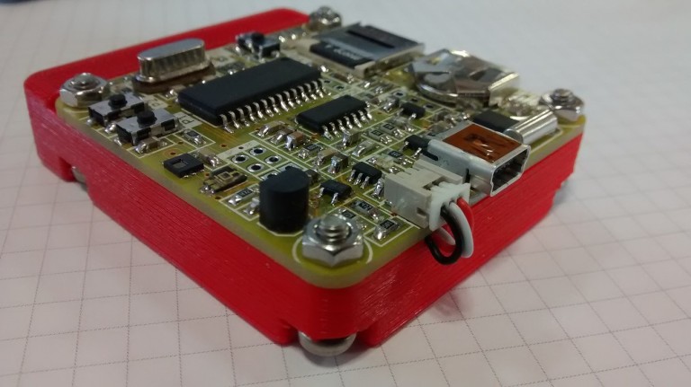
Hi all! I’m continuing here with the last board I design and now I’m continuing testing. It’s a battery-powered small datalogger based on a PIC18F2620 microcontroller. The idea comes a few months ago, talking with a friend. He needs something to monitoring temperature and humidity inside a sea container, for a three weeks travel from Spain to China. Low consumption is important, in order to have maximum autonomy with a small battery.
Portable temperature, humidity and ambient light datalogger – [Link]
Max Maxfield @ embedded.com discuss about IoT security and single chip solutions to this issue.
The Internet of Things (IoT) has the potential to change the world, but only if it’s secure. Securing the IoT is currently one of the greatest challenges for the creators of IoT devices and the providers of cloud services.
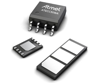
In order to address this problem, the folks at Amazon have teamed with the guys and gals at Microchip to create a seamless solution in the form of the ECC508A crypto-companion chip, which is presented in a variety of packaging options.
Single-chip end-to-end security for IoT devices connected to the Amazon cloud – [Link]
Low-cost, open-source “sip-and-puff” interface to enable new methods of expression for people with and without limited mobility. by Jason Webb:
Commercial sip and puff devices have been available for quite some time but are generally prohibitively expensive, highly specialized, limited in expressivity, require poorly-written and restrictive software and rely on clunky, out-of-date hardware that makes it difficult or impossible to integrate with modern operating systems and even basic software.
Therefore the main objective of openSip+Puff is to provide a cheap, simple, open and modern alternative input method based on the breath of a user that can be easily mapped to a variety of common actions like mouse clicks and keypresses.
openSip+Puff for people with limited mobility – [Link]
SunDuino is a Single Board Computer with integrated Battery Charger, Voltage Regulators, I2C, Digital and Analog IO. It’s main benefit is that it can run a compiled C app for years on a small battery or forever using built in solar charger. A background RTOS provides SLEEP functions for reducing operating current to 100ua while providing 125ms periodic wakeups. Sunduino comes in 25W and 10W versions to better suit your application. Take a look at the manual and Datashseet. Also the schematic and PCB layout is available for free.
Key benefits of SunDuino:
Battery charging logic is optimized for long battery life using temperature monitor. The SunDuino is a software defined charger, it supports many battery chemistries and sizes.
Low current operation provides long battery life and runtime. An internal RTOS keeps battery monitoring, power event monitoring, user C Application and SLEEP mode all operating on a 100ua drain. Small batteries can run for years.
Regulated output voltages of +5. +3.3 and +/-12 for the powering of external hardware. Radios, other processors, relays and LEDs are examples of external hardware which requires regulated voltages.
Runs compiled C Applications and various library function for complete user control of power operation. Greatly simplifies system integration.
SunDuino – Run your C application using solar power – [Link]
Texas Instruments “TI” recentlyannounced FemtoFET series.
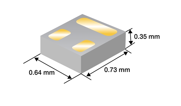
There are N-channel MOSFETS like CSD15380F3 and P-channel MOSFETS like CSD25480F3 and CSD23280F3 in this series. These transistors are SMD (Surface Mount Devices) available in a very small package, the land grid array (LGA) package.
Traditional SOT-23 package next to the CSD18541F5 LGA package. Image Source: TI
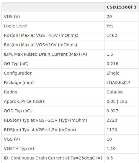
To explore this family we will highlight the FemotoFET MOSFET CSD15380F3. It has a 20V Vds, 990 mohm Rds @ Vgs=8, 500mA maximum Id, 0.5W power dissipation and ultra-small LGA Footprint 0.73 mm × 0.64 mm which make it suitable for many handheld and mobile applications.
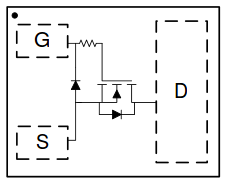
Pin-out of CSD15380F3LGA Package
The new MOSFET has Qg = 0.216 nC Ultra-low capacitance and that improves switching speeds in data line applications.
Table Source: Product Page
It’s available on Mouser for 0.47$ for 1 unit order and 0.05$ for 1,000 unit order and need 6 weeks lead time.
Via: TI E2E Community Blog
David Jones made a tutorial on the fundamentals of zener diodes over his EEVblog youtube channel.
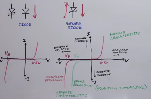
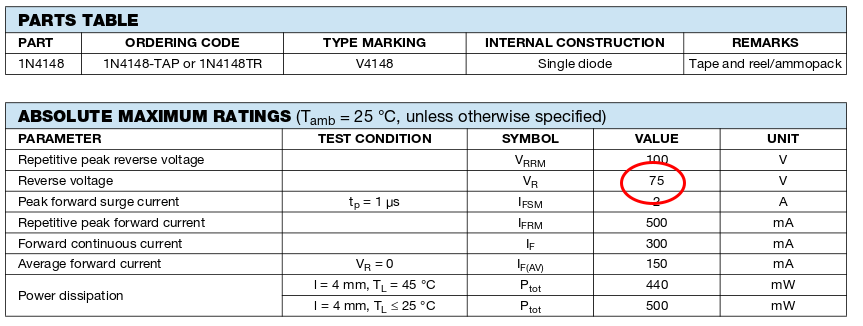
David started the tutorial comparing between zener and regular diode. Both have the same characteristics and same I-V chart, but zener is designed to work in the negative voltage region.”In theory” the regular diode can work in the negative voltage region, but the breakdown voltage, Vb the minimum reverse voltage that makes the diode conduct in reverse, is really high. For example, 1N4148 Vb=75v and this value it is not usable in practical circuits, while Vb in zeners is designed to meet our needs. So diode effectively stops current in negative region until the voltage reaches Vz where it starts to contact current.
David highlighted the difference between Avalanche breakdown and zener breakdown. When you use zener with Vr (aka Vb)<5V then you will have zener breakdown effect and above that you will have Avalanche breakdown effect.
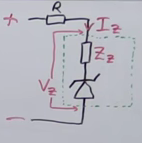
Most important electrical characteristics of zener is Vz (breakdown voltage, aka Vb or Vr), Iz and Zz ( internal impedance of the zener) that you must take them in account when you use a zener in your design.
David demonstrated the main applications of zener:
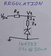
First One: Regulation To 5.1V
This is because the nature of zener. Zeners have a stable voltage when the reverse voltage reaches the Vz.
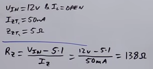
David calculated the current limiting resistor Rz value first without attaching the load.
Note: Iz and Zz value are from the datasheet of 1N4733.Vin is 12V.
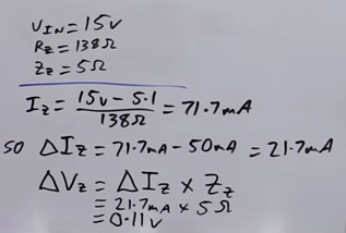
Then he demonstrated in numbers how the regulation output will change when we change Vin from 12V to 15V.
Beside the problem of output voltage variation, we can see that the zener will consume about 70mA to regulate Vin to 5.1V which is a quite considerable amount of current. So using zener for main power regulation in your circuit is not advisable. You can use some well known voltage regulation ICs like LM7805, which have a stable output and a very low quiescent current.
Zener regulation feature still very useful for low power signals.
The high current needed for zener regulation operation will also produce a high power dissipation, P= U*I = 5.1 * 0.05 = 0.255 W which is a considerable power value.
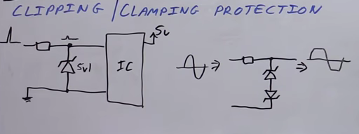
Second One: Clipping/Clamping
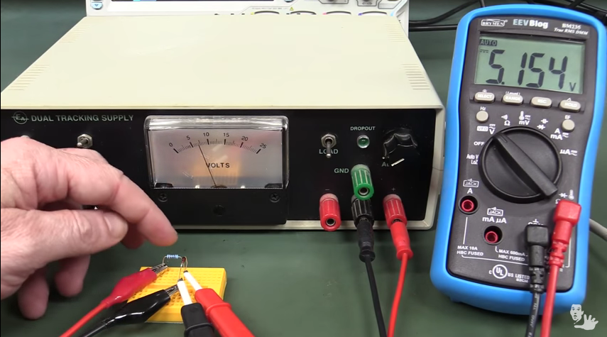
In the end of David’s video tutorial he hocked up a zener with an oscilloscope probe and showed how zener behave in practice.
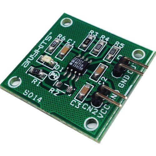
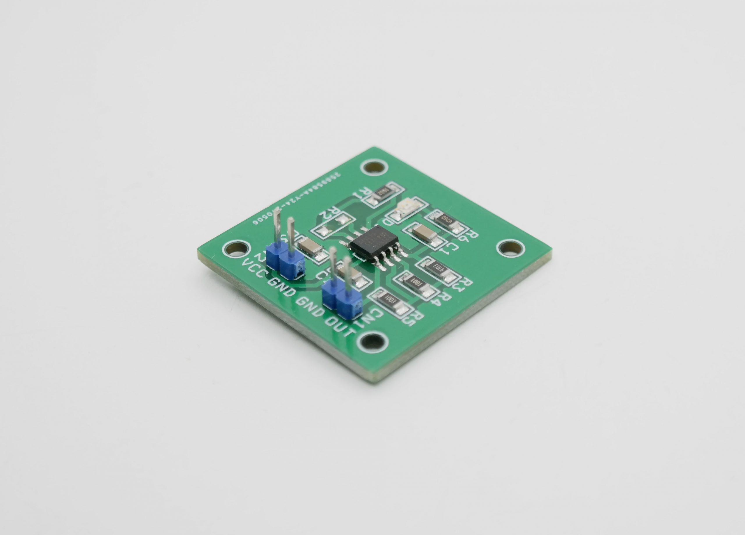
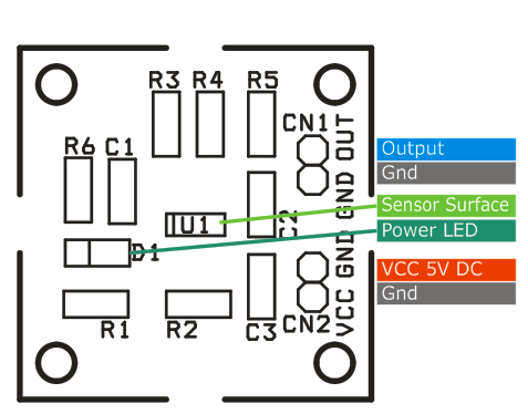
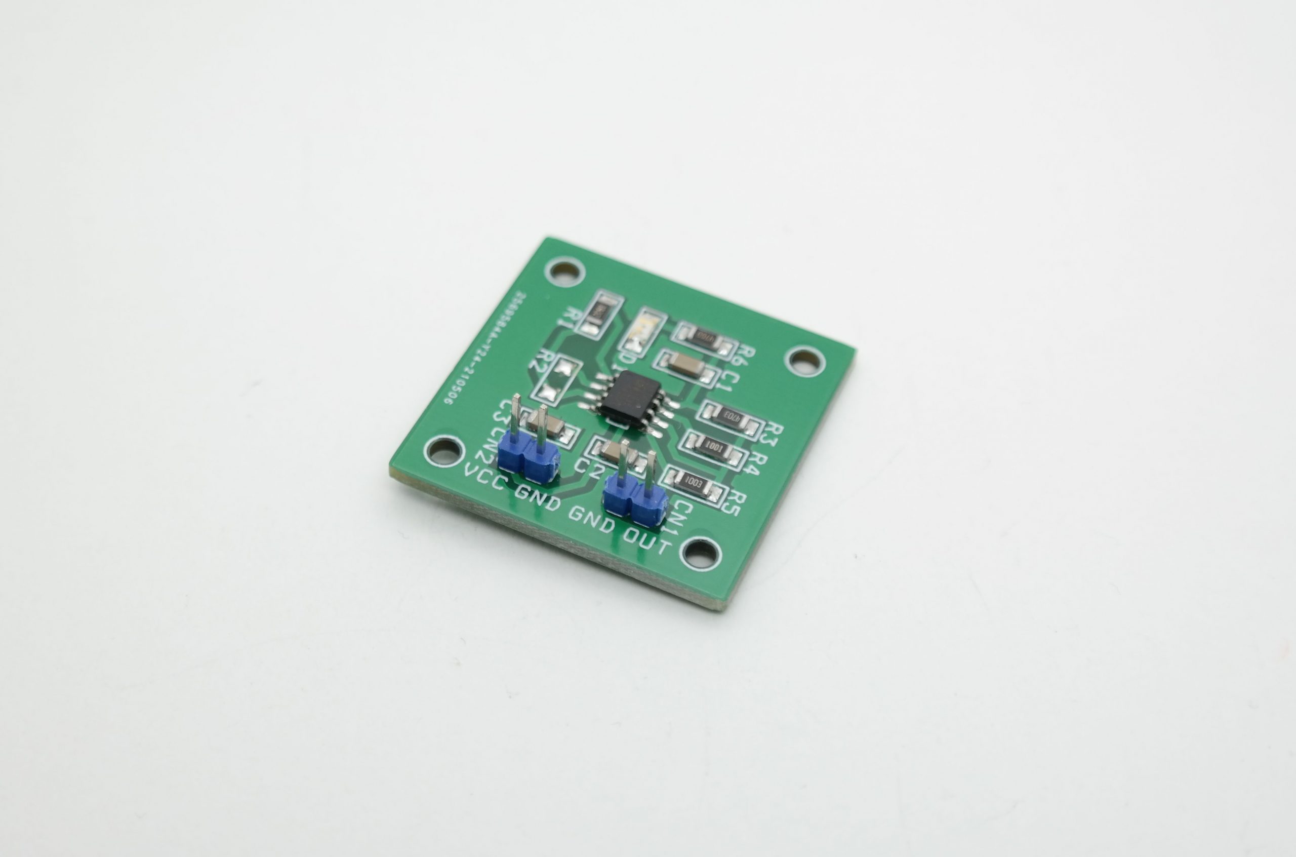
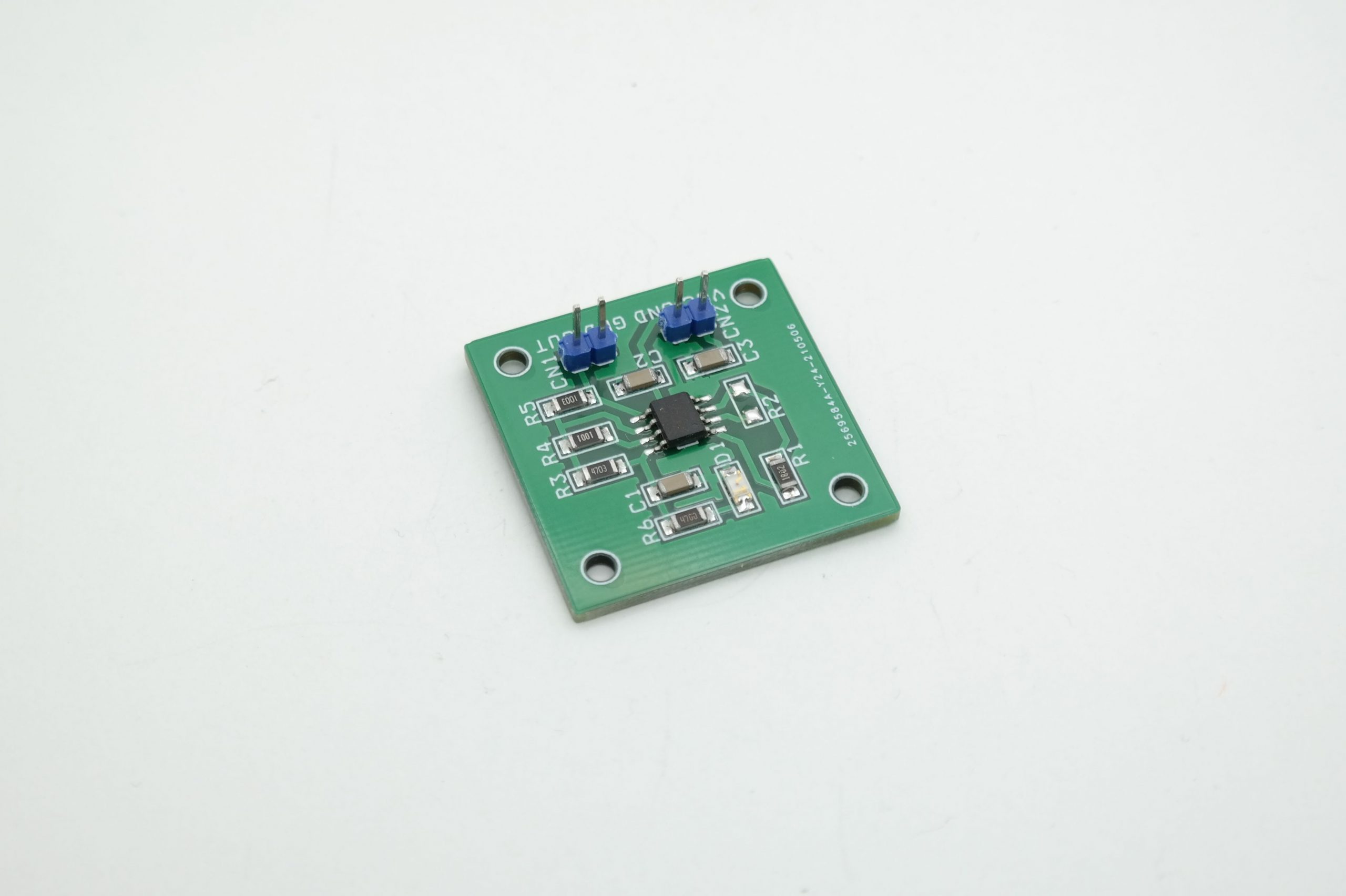
Magnetic field sensor project using AD22151 IC from Analog Devices, The AD22151 is linear magnetic field transducer. The sensor output is a voltage proportional to a magnetic field applied perpendicularly to the package top surface. The sensor combines integrated bulk Hall cell technology and instrument technology to minimize temperature related drifts associated with silicon Hall cell characteristics.
Magnetic field sensor project using AD22151 IC from Analog Devices, The AD22151 is a linear magnetic field transducer. The sensor output is a voltage proportional to a magnetic field applied perpendicularly to the package top surface. The sensor combines integrated bulk Hall cell technology and instrument technology to minimize temperature-related drifts associated with silicon Hall cell characteristics.
Features
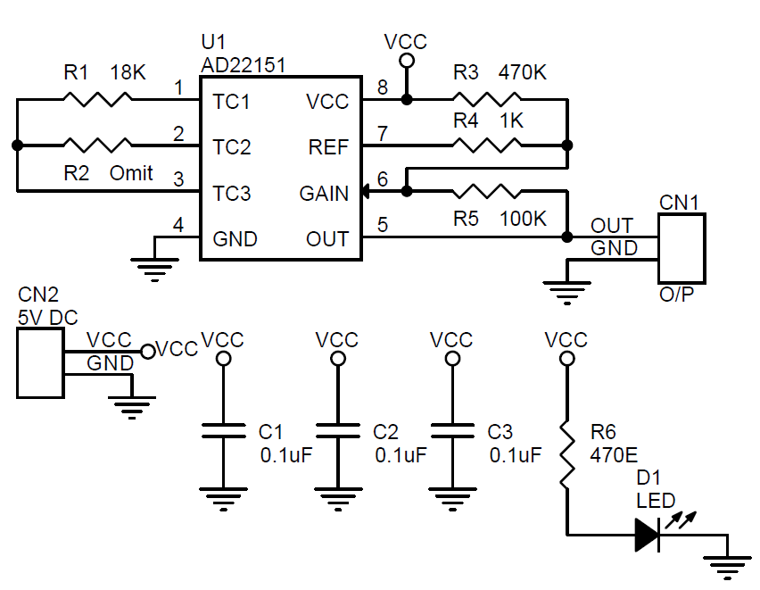
Supply 5V DC @ 25mA
Power Led On Board
Header connector for supply and output
Normal Output 1.800V
South side Magnet Output 4.800V
North side Magnet Output 0.042V
Applications
Throttle Position Sensing
Pedal Position Sensing
Suspension Position Sensing
Valve Position Sensing
Absolute Position Sensing
Proximity Sensing
Sensitivity Adjustment and Zero Gauss
The sensitivity of the sensor can be adjusted by changing some of the resistors on the board. For more information on how to calculate the resistors refer to the datasheet page 5, paragraph GAIN and OFFSET. The operation of AD22151 can be either bipolar or the Zero Gauss point can be set to a different voltage level. The gain can be set by altering resistors R3 and R5. For example, if we want to set for bipolar operation we set R2 and R1 is not placed. For unipolar operation, R1 is set and R2 is not placed. If we want to set output gain to 1.4mV/G with bipolar operation then we choose R5=R4=85k, R2= 18k, and R1=R3 =omit. This setting will give us a Zero Gauss output of 2.5V, so 2.5V/1.4mV gives us a ± 1785 Gauss output.