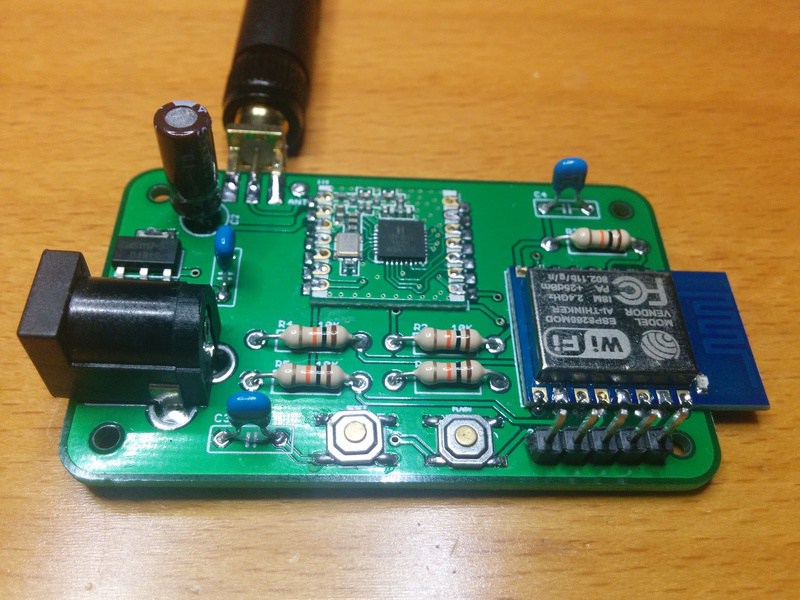
The RFM69GW is a RFM69 to MQTT gateway that uses the ubiquitous ESP8266 chip. There are two or three similar projects that I’m aware of but I’ve put together some hardware and firmware features that make it different. by Xose Pérez:
I’m using Felix Rusu’s RFM69_ATC library so it supports Monteino nodes with Auto Transmission Control feature enabled for an adaptative transmission power: longer battery life & less radio pollution
RFM69CW footprint, compatible with RFM12B and hence with old Monteinos or even with JeeNodes (untested)
Web configurable map between node messages and MQTT topics.
EEPROM persistent configuration using the awesome Embedis library by PatternAgents
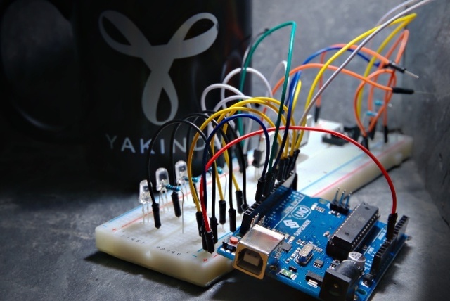
Did you ever program an Arduino? Have you ever been worried about complex control flows written in pure C? Maybe you have already heard of statecharts and state machines? In this blog post, I will show you how to program an Arduino in just 5 minutes in a model-driven way with the help of YAKINDU Statechart Tools (SCT).
Program an Arduino with State Machines in 5 Minutes – [Link]
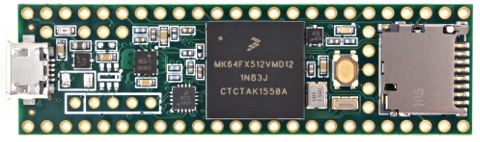
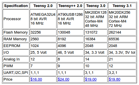
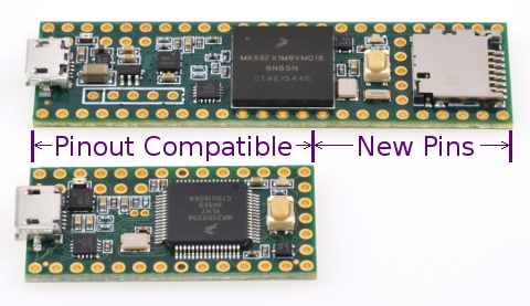
“Teensy” is a tiny size board compatible with Arduino software and libraries. Teensy 3.1 & 3.2 was the last version from Paul Stoffregen (PJRC Company) the creator of Teensy.
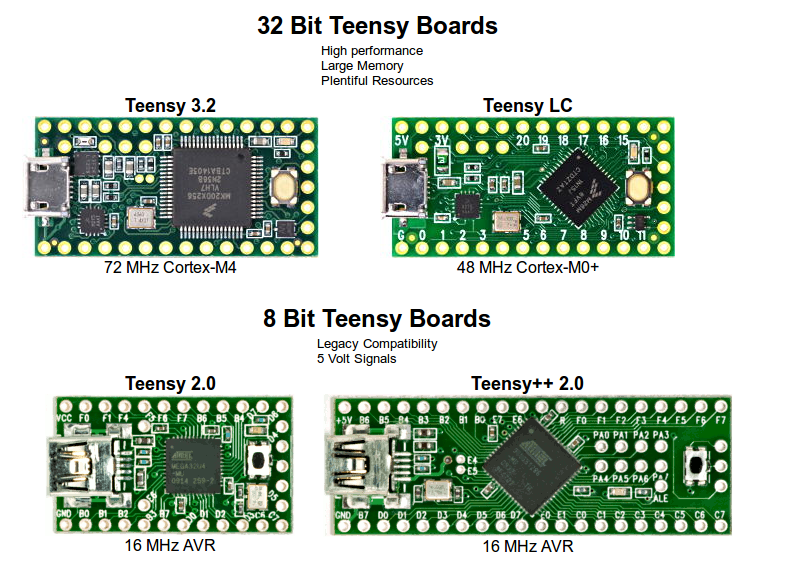
Table is from PJRC website
Paul started a Kickstarter campaign for The new Teensy 3.5 and 3.6 and until the time of preparation of this post, there are 1,697 backers and campaign raised $102,974 of the $5,000 goal with 15 days to go.
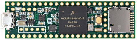
Teensy 3.6Teensy 3.5
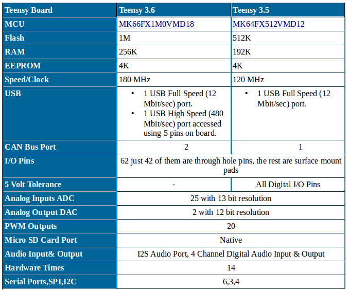
Teensy 3.5 and Teensy 3.6 have slightly differences. I made a full comparison in the bellow table:
Teensy 3.5 has a lower in features MCU (RAM, Flash, clock and some peripherals) which make it slightly cheaper than Teensy 3.6. Teensy 3.5 has 5v tolerance on all digital I/O pins.
Only Teensy 3.6 has a USB High Speed (480 Mbit/sec) port accessed using 5 pins on the board.
Teensy 3.5 and Teensy 3.6 are 6-layer PCB with 28 pins compatible with previous Teensy3.x models.
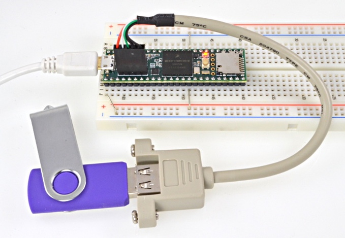
As we said, Teensy is compatible with Arduino software so Arduino IDE is the primary method used to program Teensy 3.6 and Teensy 3.5.
Paul (PJRC company) offered Teensy 3.5 for 23$ and Teensy 3.6 for 28$ for the Kickstarter campaign backers shipped in October.
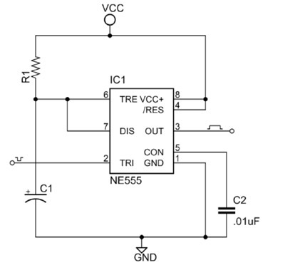
Philip Kane @ jameco.com has published an article about the famous 555 timer IC and how to configure in monostable and astable modes.
The 555 timer was introduced over 40 years ago. Due to its relative simplicity, ease of use and low cost it has been used in literally thousands of applications and is still widely available. Here we describe how to configure a standard 555 IC to perform two of its most common functions – as a timer in monostable mode and as a square wave oscillator in astable mode.
Last year Google announced “Brillo” an operating system for IoT devices with a communication protocol called “Weave”. Today, most of the technical websites are talking about the new operating system “Fuchsia” which is, according to Google brief description, a “Pink + Purple == Fuchsia (a new Operating System)”.
Fuchsia Inside
LinuxInsider website asked Google spokesperson Joshua Cruzthe about Fuchsia. His answer was: “it is a new open source project that is not at all related to Android or Chrome OS”.
Fuchsia is built on the Magenta kernel, which is based on Google’s LittleKernel project. Developers of Fuchsia described the differences between LittleKernel and Magenta in a ReadMe file.
“LK is a Kernel designed for small systems typically used in embedded applications. It is good alternative to commercial offerings like FreeRTOS or ThreadX. Such systems often have a very limited amount of ram, a fixed set of peripherals and a bounded set of tasks. On the other hand, Magenta targets modern phones and modern personal computers with fast processors, non-trivial amounts of ram with arbitrary peripherals doing open ended computation.”. So Fuchsia is not using Linux kernel like Android.
Supported Architectures
ARM32, ARM64, and x86-64 are the current supported architectures.
One of Fuchsia developers, Brian Swetland who worked on Android, BeOS and Danger, stated in one of discussion thread on Y Combinator’s Hacker News, that Fuchia soon will support the Raspberry Pi 3.
You can see the current supported targets here which are Acer Switch Alpha 12, Intel NUC (Skylake and Broadwell) and Raspberry Pi3. You can read the document for booting Fuchsia on Raspberry Pi 3 from the SDCard.
Brian Swetland showed a shot of virtual console 0 with the tail end of the boot log on an Acer Switch Alpha 12.
Image courtesy of Brian Swetland
Is It For IoT and Embedded Systems Devices?
Sascha Wolter asked in Brillo and Weave Google group, “Should we stop with Brillo and get our hands in #Fuchsia?”, and the answer was: “Sorry for not providing any updates on the progress of Brillo and Weave for a while. Don’t worry though, we are still hard at work on both of them! We want to make sure everything is finalized before releasing an update, but you will be hearing from me soon with more detailed information”.
So I think until now Fuchia is not the Brillo killer while a lot of speculations are around the target market of this new OS from Google.
According to some folks the new OS has a Flutter-based UI and run Dart programming language (I can see Dart content handler in the Git repo), and that supports the point of view saying that “Fuchisa” is not another RTOS like Brillo, it’s maybe the next Android.
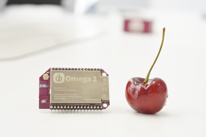
World’s smallest Linux server, with Wi-Fi built-in. Omega 2 is a Linux compute module designed specifically for building connected hardware applications. It combines, say its designers Onion, “the tiny form factor and power-efficiency of the Arduino, with the power and flexibilities of the Raspberry Pi.” By Graham Prophet @ edn-europe.com
Omega 2 development is the subject of a Kickstarter campaign, that closes on August 23 rd 2016 ( here). The projects starts with the base module, which is an SoC-based board with built-in WiFi, and extends through levels of added connectivity, and peripherals – for example, there is a ‘dock’ card that provides compatibility with Arduino-format hardware. Part of Onion’s offering is a cloud service, so that an Omega 2-based project can be fully cloud-connected and -enabled.
Crowdfunding closing on $5 Linux + Wifi tiny IoT compute module – [Link]
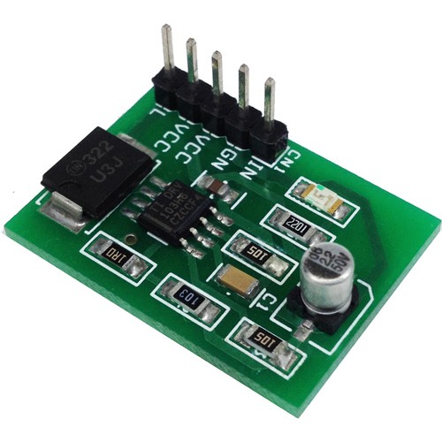
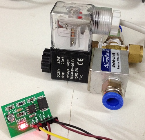
Tiny module is a PWM Solenoid and Valve driver using Texas instrument’s DRV103 low-side DMOS power switch employing a pulse-width modulated (PWM) output. Its rugged design is optimized for driving electromechanical devices such as valves, solenoids, relays, actuators, motors and positioners. This board is also ideal for driving thermal devices such as heaters, coolers, lamps, PWM operation conserves power and reduces heat rise, resulting in higher reliability. In addition, adjustable PWM allows fine control of power delivered to the load. Output delay time and oscillator frequency are also externally adjustable.
Features
Supply 8V to 32V DC
Load Capacity 1.5A
Trigger Input Voltage 1.5V to 5V DC
Thermal and Current Limit Shutdown
On Board Power LED
PWM Solenoid and Valve Driver using DRV103 – [Link]
This tiny module is a PWM Solenoid and Valve driver using the Texas instrument’s DRV103 low-side DMOS power switch, employing a pulse-width modulated (PWM) output. Its rugged design is optimized for driving electromechanical devices such as valves, solenoids, relays, actuators, motors, and positioners. This board is also ideal for driving thermal devices such as heaters, coolers, lamps etc. PWM operation conserves power and reduces heat rise, resulting in higher reliability. In addition, adjustable PWM allows fine control of the power delivered to the load. Output delay time and oscillator frequency are also externally adjustable.
The DRV103 can be set to provide a strong initial closure, automatically switching to a “soft” hold mode for power savings. A resistor, analog voltage, or Digital-to-Analog(D/A) converter can control the duty cycle. An output OK flag indicates when thermal shutdown or over current occurs.
Features
Supply 8V to 32V DC
Load Capacity 1.5A
Trigger Input Voltage 1.5V to 5V DC
Thermal and Current Limit Shutdown
On-Board Power LED
PCB dimensions: 28.25 x 20.63 mm
Applications
Solenoids
Valves
Heaters, Coolers
Lamps
Relays
Power Contactor Coils
Hydraulics and Pneumatics Systems
Note: PWM Duty Cycle, Output Delay, Frequency Adjust are adjustable from external resistors
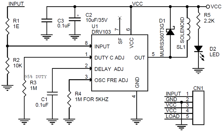
Oscillator Frequency range 500Hz to 100Khz, the default set to 5Khz, Frequency can be altered by changing R4 ( Refer to Datasheet for more details)
Delay Output: Default delay set to approx. 100 ms, Delay can be adjusted by changing Capacitor C1
Duty Cycle is adjustable 10% to 95% , the default set to 95% can be altered by changing R3 (Refer to Datasheet for more details)
Schematic
Parts List
SR
QNTY
REF
DESC
MOUSER
1
1
CN1
5 PIN HEADER CONNECTOR
523-G800W303018EU
2
2
C1,C3
0.1uF SMD 1206
80-C1206C104K6RACTU
3
1
C2
10uF SMD 35V
UWT1V100MCL1GB
4
1
D1
MURS360T3G SMD
78-VS-4ECU06-M3/9AT
5
1
D2
LED RED SMD 1206
710-150120RS75000
6
1
R1
1R SMD 1206
RT1206FRE071RL
7
1
R2
10K SMD 1206
RT1206FRE0710KL
8
2
R3, R4
1M SMD 1206
603-RT1206FRE071ML
9
1
R5
2.2K SMD 1206
603-RT1206FRE072K2L
10
1
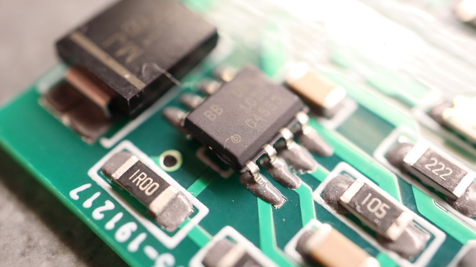
U1
DRV103 SMD SOIC8
595-DRV103U/2K5
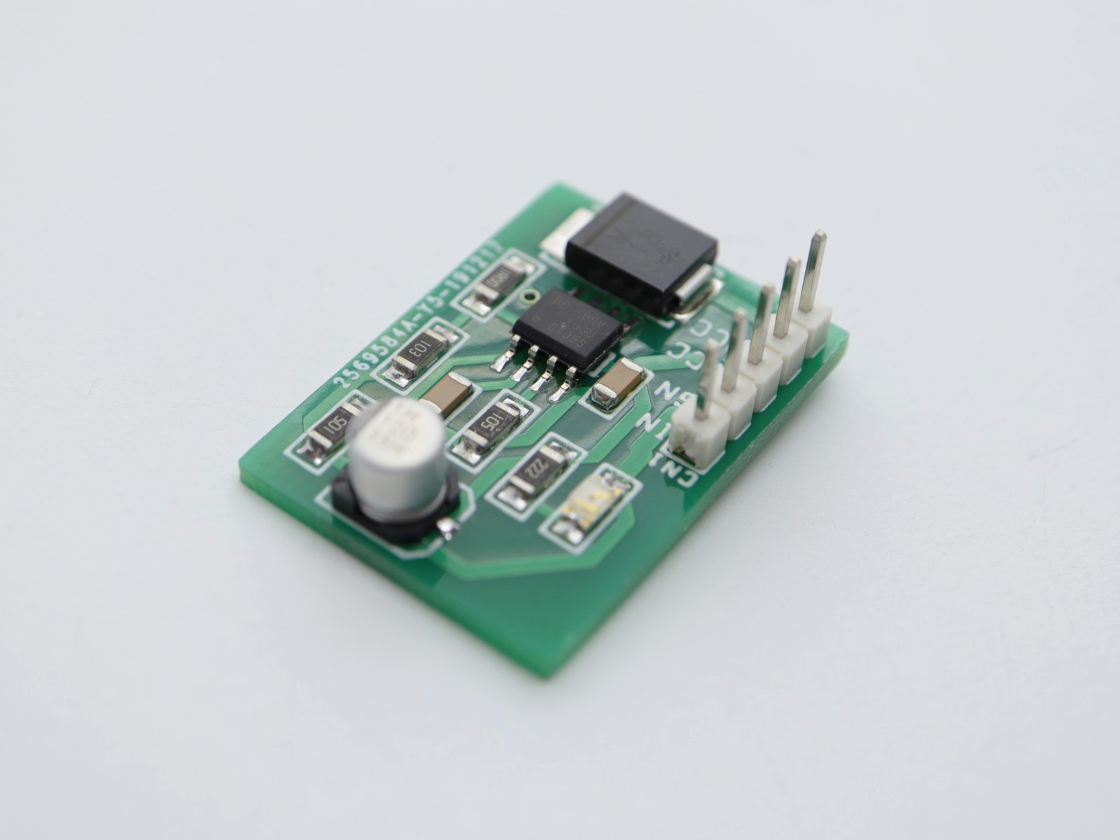
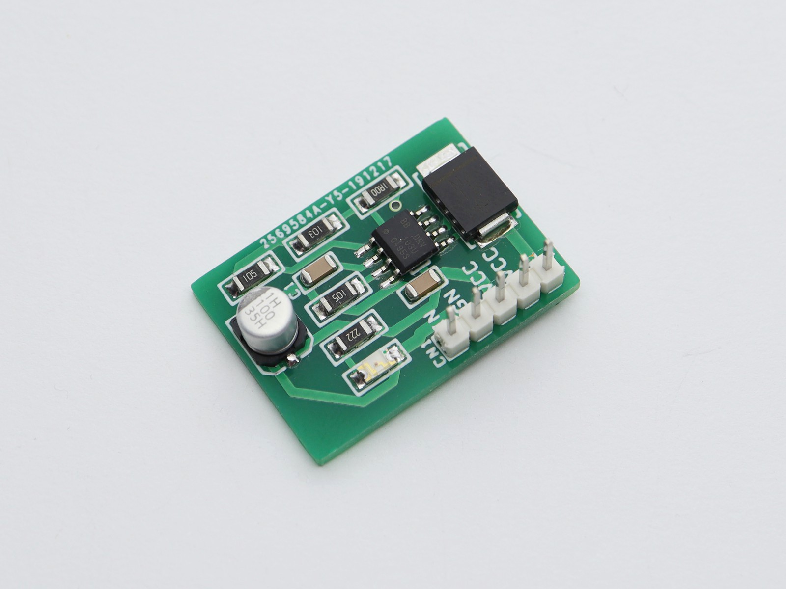
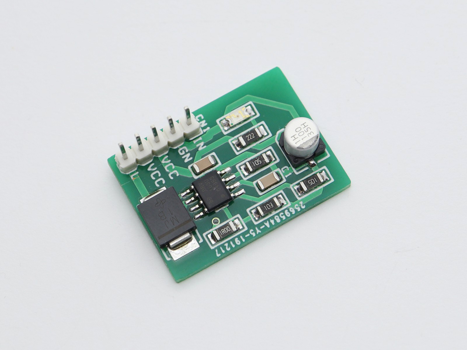
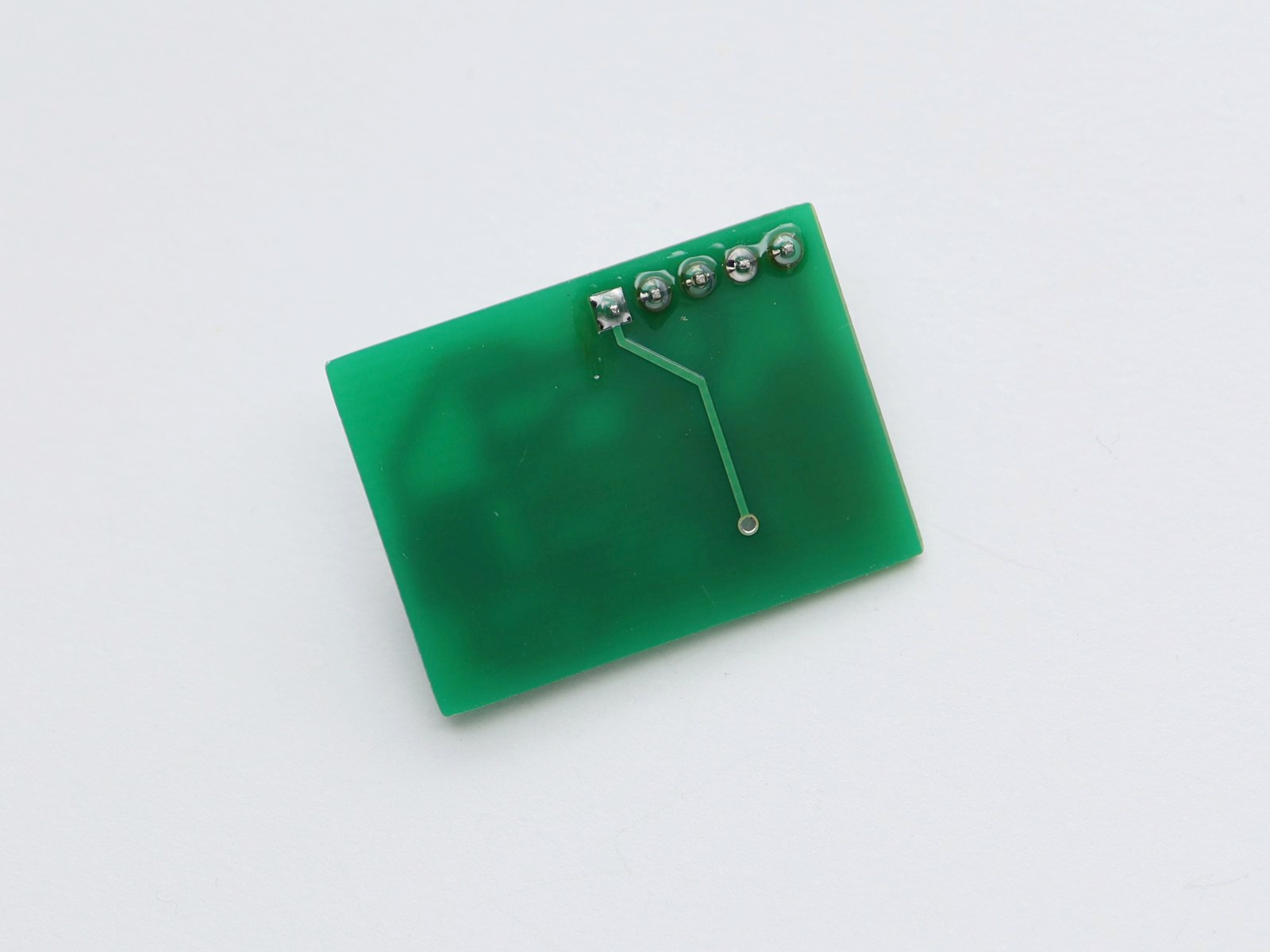
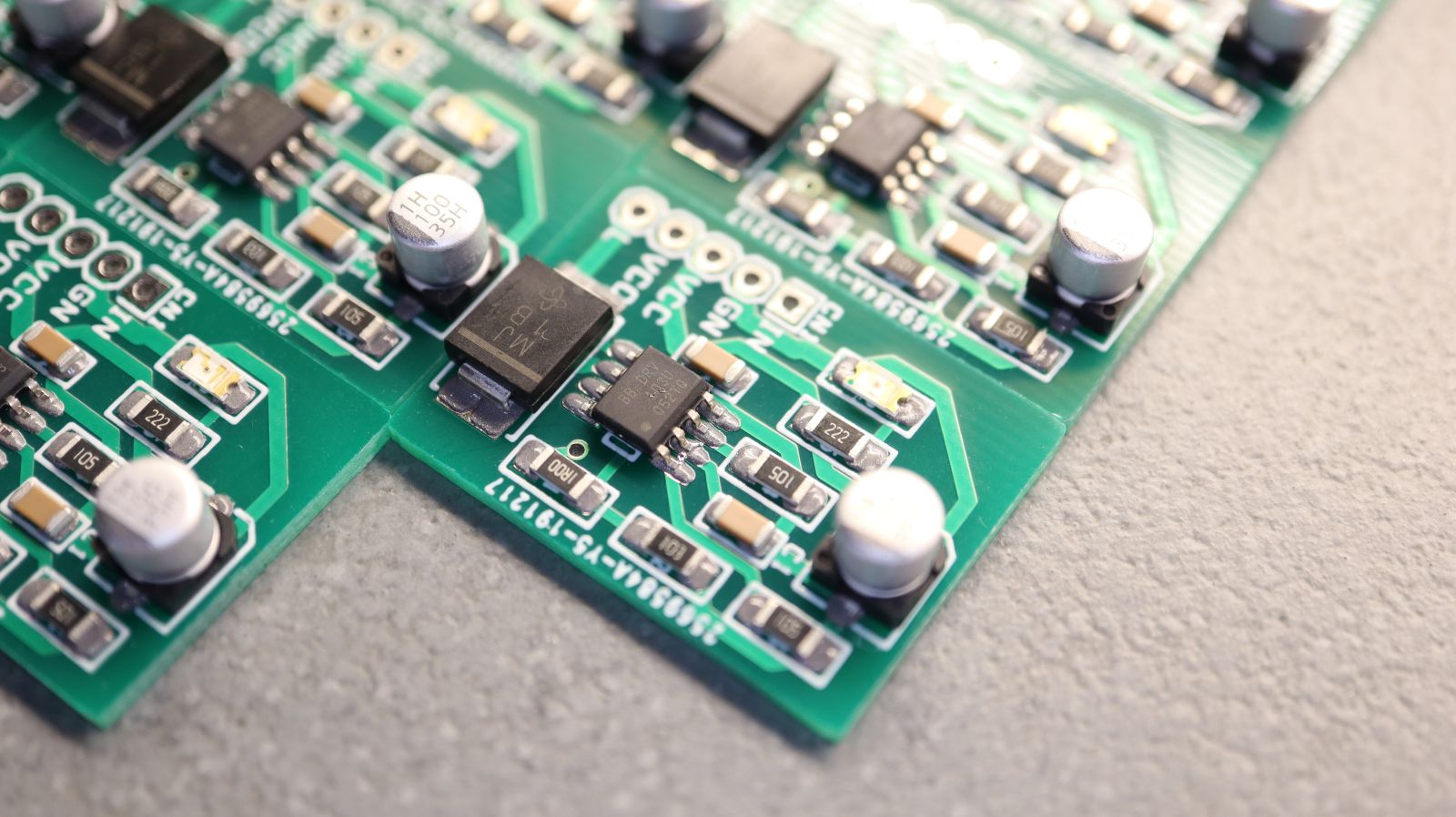
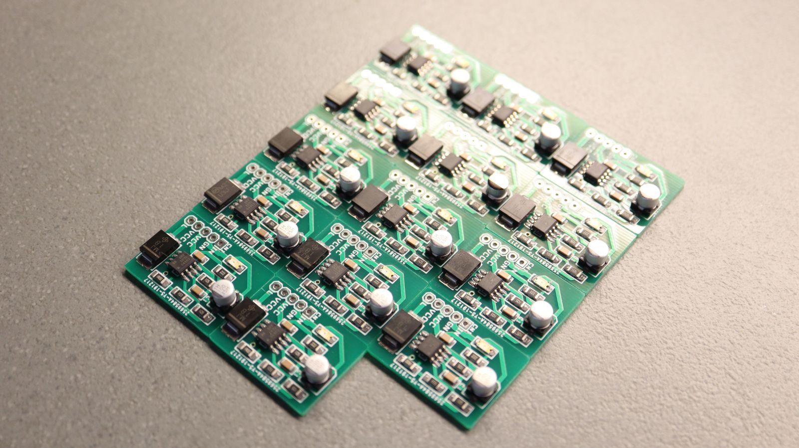
Photos
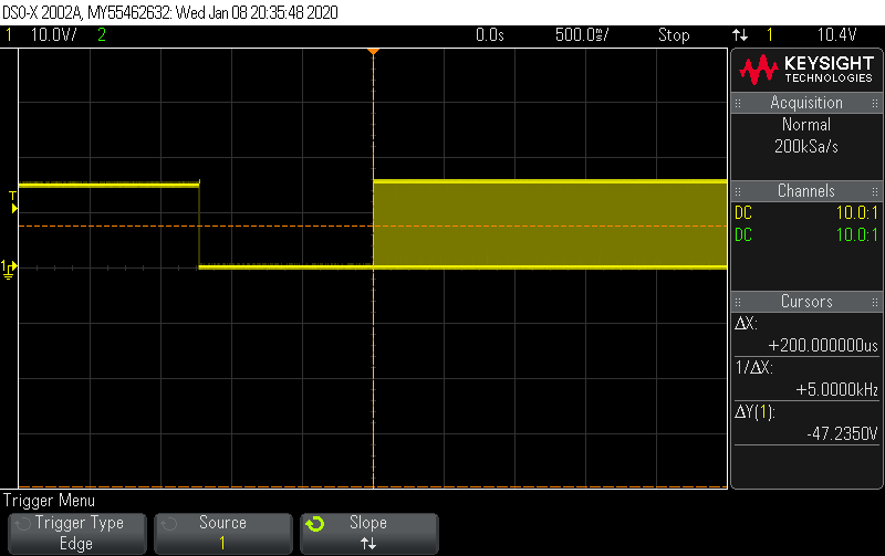
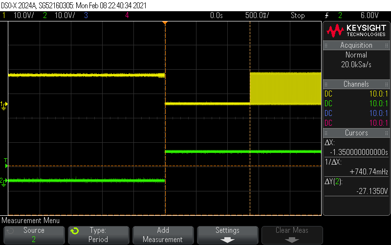
Measurements
Vout on the solenoid. We see that goes ON and after some time it starts PWM production to retain the ON state but with lower dissipated power and thermal stress.CH1: Vout on the solenoid – CH2: INPUT triggering voltage. We can see that after the board is triggered solenoid goes on for about 1 sec and then switches to PWM generation to hold the coil energized with low power consumption.
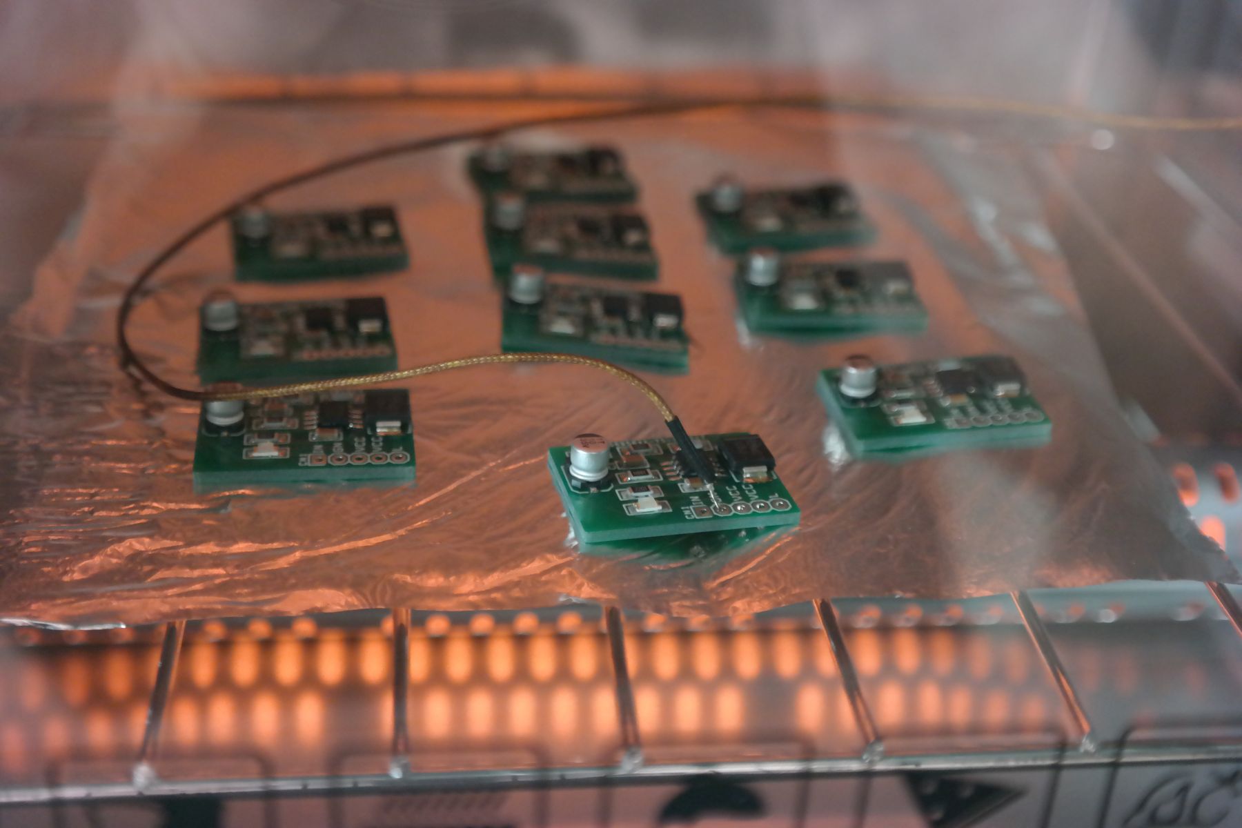
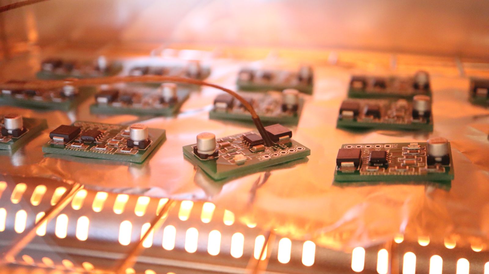
Manufacturing
Reflow soldering of 10x PCBs on our DIY reflow oven