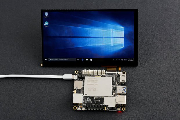
Imagine being able to use Windows 10 on a Single Board Computer (SBC) right out of the box – that’s LattePanda. by Cabe Atwell @ makezine.com:
Makers at Latte, a Shanghai-based startup, were frustrated at the lack of tools available to makers looking to create Windows-based projects. That, despite what you are thinking, does have some relevance. Windows being the most popular consumer OS on the planet, has a vast catalog and a huge support community. In response, the team created LattePanda, a palm-sized, quad-core (Intel Cherry Trail 1.8GHz) full Windows 10 computer.
LattePanda Puts Windows 10 on a Single Board Computer – [Link]
The C library function printf() is one of the common used functions in embedded systems world to debug the code in real time over a serial connection. Using the printf() over serial is under debate and may not be optimal for embedded systems and that’s what Jacob Beningo over EDN tries to demonstrate.
The first problem with using printf() is the need to bring a standard C library into the software which consumes a lot from RAM and ROM/Flash which are limited in size. The second problem is during the execution time of printf() where system becomes blocked until all characters have been transmitted.
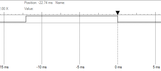
Timing Diagram For Printing “Hello World!” Using printf() Through A UART At 9600 Baud – Image courtesy of EDN
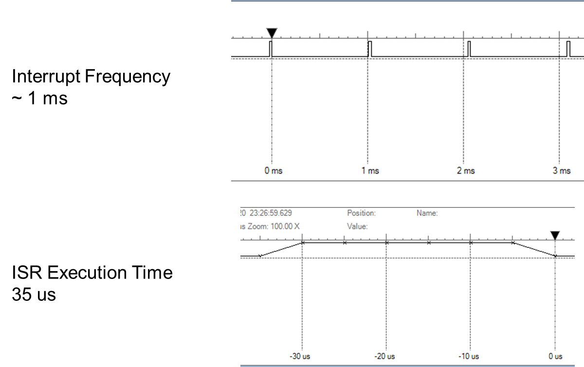
Jacob addressed some solutions and alternatives. One of them was developing a non blocking version of printf() that uses an interrupt service routine to handle transmission of buffer content.
Performance Of The Non-blocking Version – Images courtesy of EDN
Another solution is to use SWD (Single Wire Debugger) interface, a 2-pin debug port for ARM MCUs, which minimizes software overhead where an internal buffer gets filled and the debug hardware automatically handles transmission to the debug probe. You can read more about SWD in ARM website.
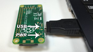
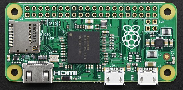
Raspberry Pi Zero is the smallest member in Raspberry Pi single-board computers family with a single-core 1 GHz processor chip, a micro-SD card slot, a mini HDMI port and two micro USB ports (one for power, one for USB). A tutorial in CircuitBasics demonstrates how we can get an Internet access for Raspberry Pi Zero from our computer over USB, because Raspberry Pi Zero doesn’t have an Ethernet connector RJ45 to have direct access to network.
Raspberry Pi Zero – Image courtesy of Adafruit
The trick used here is to recognize the Raspberry Pi Zero as a USB/Ethernet gadget, in other words using Ethernet emulation over USB.
What you need:
Micro USB to USB adapter.
Bonjour software installed on your computer to recognize USB and ethernet devices.
A micro SD card with an image of Raspbian Jessie Full or Lite (version 5-10-16 or later).
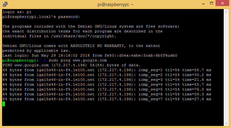
In order to do the trick of getting the Internet access over USB you need to setup up Pi Zero OTG before connecting Pi Zero with USB.
When you connect it with USB, after setting up the OTG, you will see the PI Zero under “Other devices”->“RNDIS/Ethernet Gadget” from device manager.
The last step is to set up shared Internet access with your USB/Ethernet gadget, here it’s Pi Zero, from “Network Connections”.
Communication with Pi Zero is done by using PuTTY.
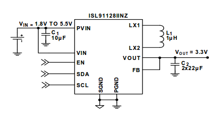
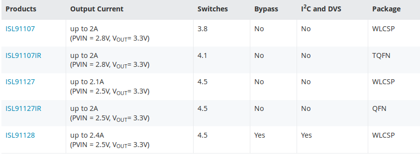
If your application requires a changing supply voltage, then this new IC is ideal for you. Intersil announced the ISL91128, a new buck-boost regulator. The new regulator has an I2C interface to select a broad set of features including output voltage range and slew rate. This eliminates the need of feedback resistors and allows the reuse of the same design for multiple output voltage needs.
The input voltage range is from 1.8V to 5.5V, and the output voltage range is from 1.9V to 5.5V with output current up to 2.2A. ISL91128 has 2.5MHz switching frequency. It is fully protected for short-circuit, over-temperature and undervoltage, according to the datasheet.
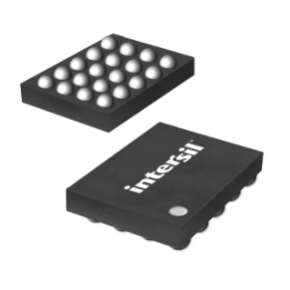
ISL91128 is available in a small 2.15mm x 1.74mm WLCSP package.
Intersil provides ISL91128IIN-EVZ, an evaluation board for ISL91128. ISL91128 is part of ISL911xx family of buck-boost/boost regulators.
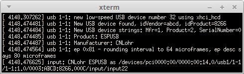
ESP8266EX and even the new ESP32 SoC lack a USB hardware transceiver, so [CNLohr] decided to develop a USB software stack for ESP8266. After a quick search, I think it is the first try to do a USB software stack for esp8266. USB software stack is a firmware-only implementation of a USB. ESPUSB works in a similar way of V-USB for AVR MCUs.
This USB Stack uses D- on GPIO 4 and D+ on GPIO 5 and only operates with low-speed USB. To run ESPUSB on ESP8266 it will need about 317 byte of SRAM and 1422 byte from flash/IRAM.
USB Enumeration Using ESPUSB – Images courtesy of cnlohr
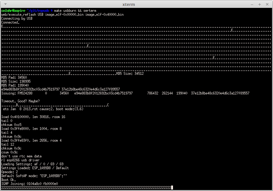
[CNLohr] said that he could flash ESP8266 using the ESPUSB.
Flashing ESP8266 Using ESPUSB – Images courtesy of cnlohr
[CNLohr] described in a video the code of ESPUSB and how he developed it.
A forum for discussion for ESPUSB was created in ESP8266 website.
You can reach the source code of ESPUSB project on the GitHub repository.
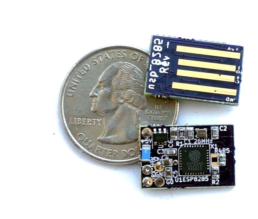
UPDATE(2/8/2016): [CNLohr] published a tweet, containing a photo of a PCB module for ESPUSB, it’s a small stick that can be plugged into USB directly. It uses ESP8285 SoC, same as ESP8266EX one but with built-in flash memory.
He also uploaded a video on Youtube showing the new PCB plugged into his laptop which is detected as HID mouse device using the ESPUSB USB software stack. He controls the mouse pointer over WiFi using an application from his phone.
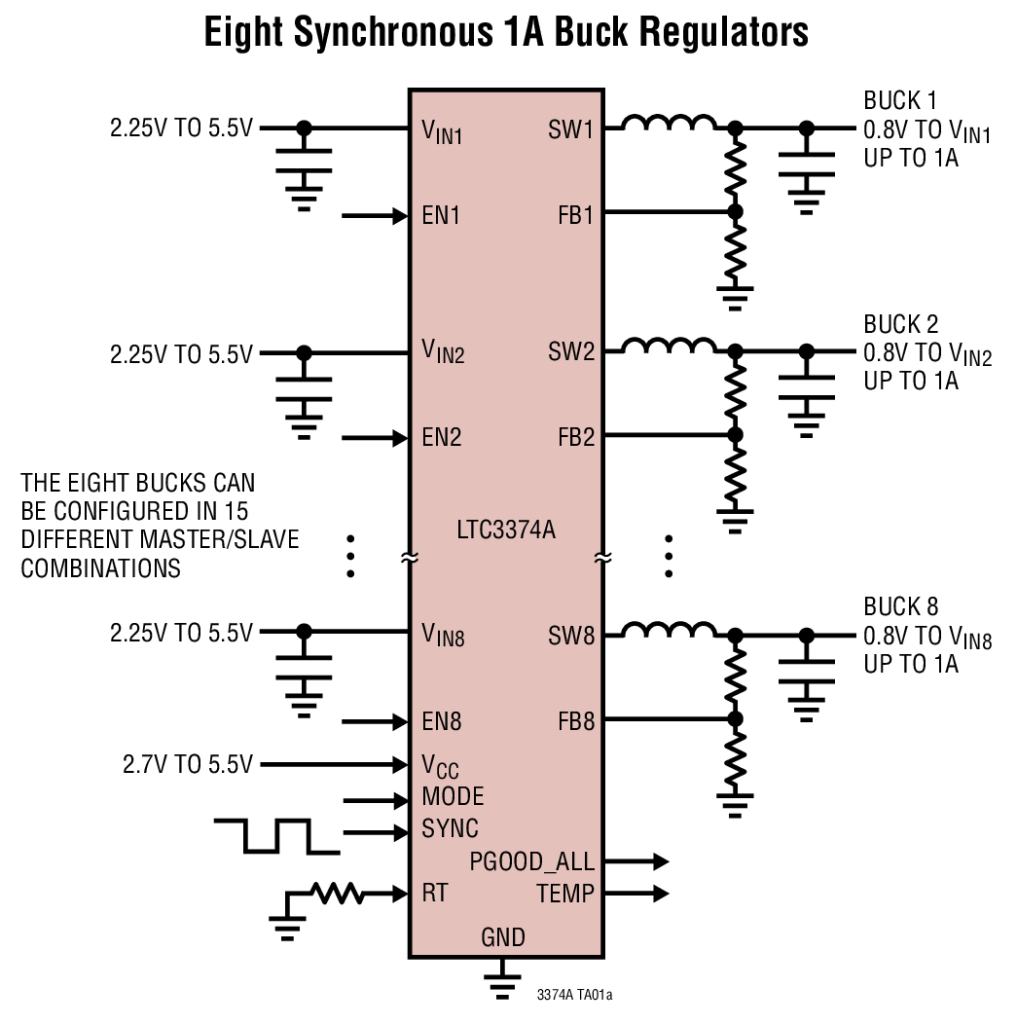
Aimed at systems requiring multiple low-voltage supplies, Linear Technology’s LTC3374A can be configured to supply two to eight independent regulated outputs with 15 possible output-current configurations. Each of the eight synchronous 1-A buck converters is powered from an independent 2.25-V to 5.5-V input supply. Output voltage range is 0.8 V to VIN. by Susan Nordyk @ edn.com
The LTC3374A is well-suited for a variety of multichannel applications, including industrial, automotive, and communication systems. Along with a peak efficiency of 94%, the device provides one output with ±1% voltage accuracy and up to seven additional outputs with ±2% accuracy. Up to four adjacent buck regulators can be combined in parallel to provide up to 4 A of output current with a single shared inductor by connecting their VIN pins together, their SW pins together, and by connecting the slave bucks’ FB pins to the input supply.
Power supply IC packs eight buck regulators – [Link]
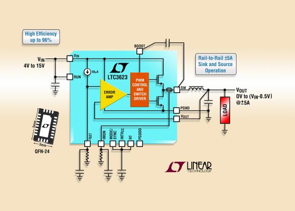
LTC3623 is a ±5A high efficiency, current mode synchronous buck regulator that is adjustable from 14.5V down to 0V output with a single resistor. Its architecture uses a 50 µA current reference, combined with a single resistor, to set the output voltage. by Graham Prophet @ edn-europe.com
The LTC3623’s 4V to 15V input voltage range is suitable for dual-cell Li-Ion applications, and fixed 5V and 12V intermediate bus systems. Low R DS(ON) integrated N-channel power MOSFETs (60mΩ top & 30 mΩ bottom) and synchronous rectification deliver efficiencies up to 96%. The device’s design allows dynamic adjustment of output voltage from 0V to V IN – 0.5V, offering virtually rail-to-rail performance.
Rail-to-rail step-down regulator sinks/sources ±5A from 0V to 14.5VOUT – [Link]
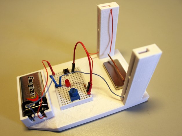
Fabian Gebhart shared his Lorentz Force experiment on Thingiverse:
Don’t you love it? Magnetism? Electronics? And 3d printing? In this project I combine all of them together to a little but spectacular do-it-yourself experiment. With just a few components and the 3d printed part you will be able to build your own Lorentz Force Experiment.
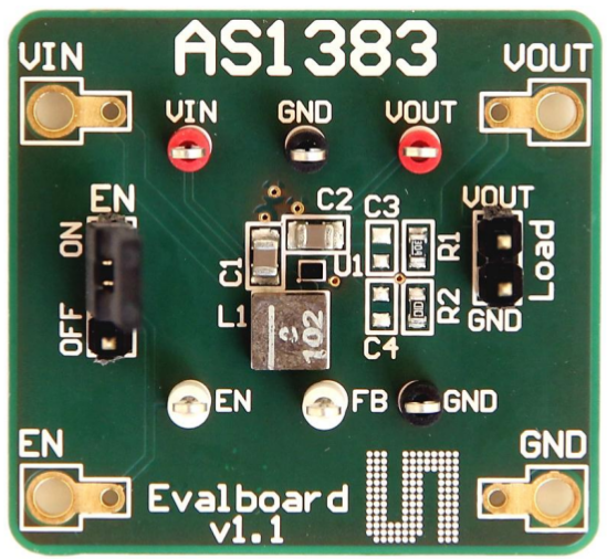
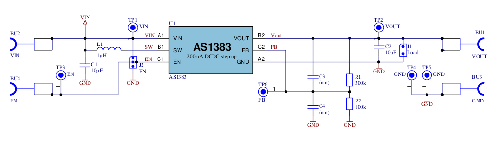
If you have a single Li-Ion battery powered application, then you need to think about using AS1383 in your design.
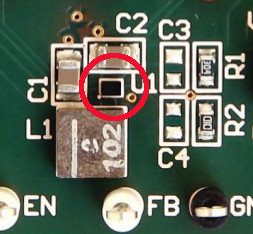
AS1383 is a DC-DC boost converter comes in a 6-pin WL-CSP package with 0.4mm pitch, a very small package suits the limited space applications. In the below image, you can compare the WL-CSP package with the 0805 SMD capacitor to know how small it is.
AS1383 And 0805 Capacitors
AS1383 uses 3.5MHz switching frequency and this high frequency allows the usage of a low profile inductor with only 1μH.
The input voltage range is from 2.7V to 5.5V and The output voltage range is from 2.7V to 5.0V with 200mA output current. It has an enable input pin to reduce the supply current to < 1μA.
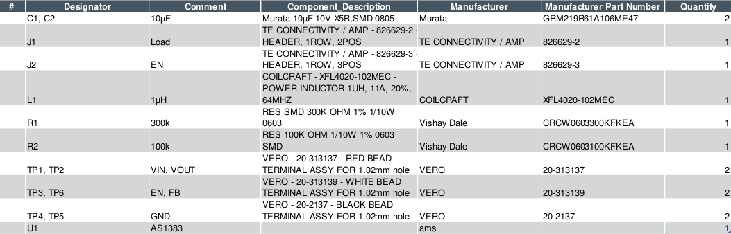
AS1383 is available in three options:
AS1383-BWLT-AD an adjustable Vout version.
AS1383-BWLT-45 a 4.5V fixed Vout.
AS1383-BWLT-50 a 5.0V fixed Vout.
The output voltage in the adjustable version can be selected with external resistor divider connected to the FB pin.
beningo.com discuss about the future of C language and it’s use in embedded systems.
The C programming language has been with embedded software developers since its creation in 1972. Ever since then C has been a blazing constant, surviving even the big push in the late 90’s and early 21st century to move to C++ or other object oriented languages. Undoubtedly, C will continue to be a foundational language for embedded systems but over the last year, the language has begun to see a decrease in popularity.