IRis – An Infrared Sensor using Photodiode amplification Circuit

IRis_PCB

[devttys0] designed a sensitive IR detector for capturing weak infrared signals. He shared in detail how he designed the circuit, beginning from the basic components, walking through solving the problems and finally ended up with a complete working circuit.

Craig Heffner/[devttys0] built this circuit for a friend’s Defcon talk, Blinded by the Light, the talk concerned about the emitted IR signals from the IR proximity detector in our devices like mobiles, and how we can identify the type of the device/OS using these signals.

Craig wanted to build a general purpose IR detector to capture and analysis the raw IR transmissions where IR receivers is designed to sense the modulated IR signals at 36-38 kHz. “But there is so much more to the world of IR than this” Craig said.

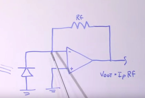
The first basic idea in the design is to use transimpedance amplifier which is basically a current-to-voltage converter.
When photons strike the photo diode, it will actually emit charge carriers, so the output of this sensor is a current. The output voltage (Vout= Ip*Rf) is linear in respect to the current.

IRis_cir1

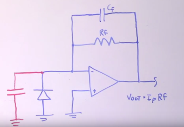
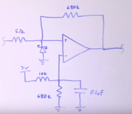
The major problem with this particular configuration is the unwanted high frequency oscillation, so a capacitor was added in parallel with the feedback resistor.

IRis_cir2

The next problem solved by Craig, is the saturation of the amplifier in high and low side by adding some bias resistors just to keep the reference voltage of the positive input of the op-amp at just under 200 millivolts.

To prevent saturation in high side he added three diodes, in fact three JFETs configured as diode, in the feedback path. The reason of using JFET configured as a diode is that it has less leakage current than normal silicon diodes, so when the voltage exceeds 3*0.7=2.1V then they short the feedback resistor, this point is important in our design because it has a current flow from photo diode.

The last thing to solve in first stage of the design is the problem of constant current from ambient light, which will generate a DC component in the output. So Craig added a high pass filter in the output.

IRis_cir3

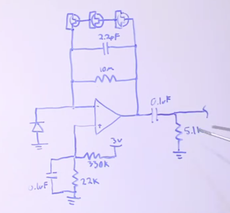
Now the circuit will still have some analog signals in output, noise and some negative spikes. So he cleaned things up by using a comparator with a Schottky diode in the non-inverting input to omit the negative pulses less than 0.2 Volt.

IRis_cir4

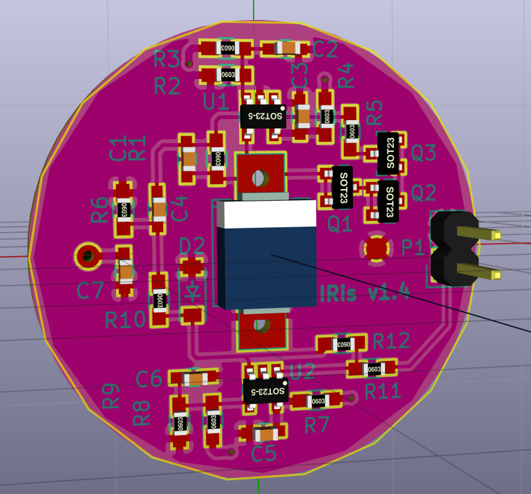
To see the full details of the design you can see the video below, and also you can reach the design files (SCH & PCB) over Github.

In addition, you can see the references pointed by Craig in his site analogzoo.

https://www.youtube.com/watch?v=FtdJ4e973bk &rel=0

HT48R002 A Very Cheap OTP MCU as Low as $0.085/Unit

A highlight from CNXSoft about Holtek HT48R002 MCU as the cheapest MCU.
HT48R002 is a 8-Bit OTP (One Time Programming) MCU with the following key features (datasheet):

  • 8-bit RISC MCU @ 8MHz.
  • 1K x 14-bit ROM (OTP).
  • 64 x 8-bit RAM data memory.
  • 6x I/O including 1x external interrupt pin, and 1x 8-bit timer.
  • Two oscillators –  Internal high speed RC: HIRC; Internal low speed RC: LIRC.
  • Fully integrated internal 8MHz oscillator requires no external components.
  • Low voltage reset function Operating Voltage – 2.3 to 5.5V.
  • Package types: 8-pin DIP/SOP, 10-pin MSOP and 16-pin DIP/NSOP

T48R002-8-SOP

As we mentioned, this MCU has OTP ROM which means that you can program it with your code just one time. If your end product will not have any update in the firmware, then OTP MCUs will be a good choice for you.

If you’re still searching for another cheap MCU, not OTP one, that costs $0.32 per unit for 1k orders, it’s PIC10F200 from MICROCHIP a 8-bit MCU with 256B flash and 16B RAM, available in either SOT-23 or 2×3 DFN packaging.

Via: cnx-software

DIY ECG with 1 op-amp

IMG_7570-1-640x480

A DIY ECG made from single op-amp (LM741) and 5 resistors by Scott Harden:

I made surprisingly good ECG from a single op-amp and 5 resistors! An ECG (electrocardiograph, sometimes called EKG) is a graph of the electrical potential your heart produces as it beats. Seven years ago I posted DIY ECG Machine on the Cheap which showed a discernible ECG I obtained using an op-amp, two resistors, and a capacitor outputting to a PC sound card’s microphone input.

DIY ECG with 1 op-amp – [Link]

PCB layout tips for thermal vias

thermal-vias

Paul Rako @ edn.com discuss about thermal PCB layout tips.

Texas Instruments’ WEBENCH is a neat program, especially because it has Mentor Graphic’s FloTherm built in to help you see the hot spots in switching regulators. This is what taught me that a modern buck regulator will have more heat coming out of the catch diode than the pass FET. It made perfect sense once I saw the heat diagram. After all, a diode has 0.6 to 0.9V across it, while a modern FET has such low on-resistance it hardly drops any voltage at all.

PCB layout tips for thermal vias – [Link]

Space Invaders FPGA Game

img_0678

Patsiatzis Nikos and Katsaros Nikos build the space invaders game using a ZedBoard FPGA. The project’s code is available on github.

This two person project was completed through the course of Embedded Systems at the University of Thessaly, Department of Computer Engineering. In the context of this game we implemented the classic space invaders game using a zedboard fpga. The code is in Verilog and you can find it on github . The project consists of 3 parts. First the connection with the monitor through the vga interface, the game logic and the sprite memory modules.

Space Invaders FPGA Game – [Link]

An isolated analog input for Arduino

VF1 isolated converter

Giovanni Carrera designed a circuit that accepts input voltage from about 20mV to 5V or a current of 4 to 20 mA and converts it to a isolated frequency signal.

A voltage to frequency converter can realize an opto-isolated analog input for Arduino or other microcontroller systems. This circuit is particularly suitable for industrial control plants with 4-20mA sensors.

An isolated analog input for Arduino – [Link]

How to Measure LUX With Arduino

FZW2RM8IRF7SHVN.MEDIUM

In this tutorial uses the Adafruit TSL2561 sensor to measure LUX with Arduino.

The TSL2561 luminosity sensor is an advanced digital light sensor, ideal for use in a wide range of light situations. Compared to low cost CdS cells, this sensor is more precise, allowing for exact lux calculations and can be configured for different gain/timing ranges to detect light ranges from up to 0.1 – 40,000+ Lux on the fly.

How to Measure LUX With Arduino – [Link]

How to Set Up WiFi on the Raspberry Pi

circuitbasics.com show us how to setup a Wifi dongle using SSH connection.

Now I’ll explain how to use that SSH connection to setup a WiFi dongle so you can run your Raspberry Pi wirelessly from a remote desktop application. This is a really useful way to set up your Raspberry Pi, because you will be able to access your it over the internet from anywhere in the world. You can use it from your iPhone, iPad, or Laptop from anywhere with an internet connection.

How to Set Up WiFi on the Raspberry Pi – [Link]

Soft Latch Power Switch Circuit

Dаvid Jones through his Youtube channel EEVblog described in detail how to design a cheap soft latch power switch circuit, using one push button switch to toggle your circuit power on and off with the following design requirements:

  1. Zero power when off.
  2. One on/off switch.
  3. Standalone(no MCU).
  4. General components only (Diodes, Transistors, ..ect).
  5. Minimal parts.

First Basic Circuit

SLPW_cir1

A passing transistor is between the input and the output, with another latching transistor.

When we initially power on the circuit, it will be off because the passing transistor is off and so the latching transistor is off (like the egg and chicken). When we turn on the “ON” switch, the passing transistor is on, so the current flows from input to output and therefor the latching transistor is on. To turn it off, press the “OFF” button and the latching transistor is off, and the passing transistor is off.

SLPW_cir1H

First design uses 2 switches and we are looking forward a circuit with one switch only, so let us get a look to the next circuit design.

Second Circuit

SLPW_cir2

When we push the button, the transistor connected to the gate of passing MOSFET will be on, and therefor the passing transistor will be on, on the right side the BJT will be on driving the line down to ground. So next time when you press the the button the transistor connected to gate will be off.

The capacitor connected to base of right side transistor is used to prevent the oscillating on/off while the pressing of the button needs milliseconds and the transistors works much faster.

To see an experiment of the design and to learn more details, check David’s video bellow:

TOP PCB Companies