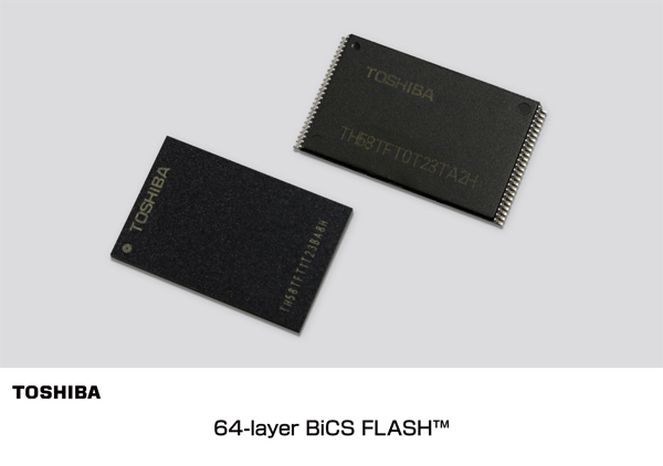
Toshiba will start mass production of 64-layer 3D NAND, BiCS3, with 3-bit-per-cell technology and a 64GB capacity in the first half of 2017. The applications of this new massive storage chip include enterprise and consumer SSD, smartphones, tablets and memory cards. This achievement succeeds the 48-layer BiCS FLASH one.
Western Digital, the well known industry-leading provider of storage technologies, recently announced world’s first 64 Layer 3D NAND. “BiCS3 has been developed jointly with Western Digital’s technology and manufacturing partner Toshiba. It will be initially deployed in 256 gigabit(32GB) capacity” according to Western Digital’s press release.
In the same context, Samsung seems going to start production of 64-layer 3D NAND at the end of this year 2016.
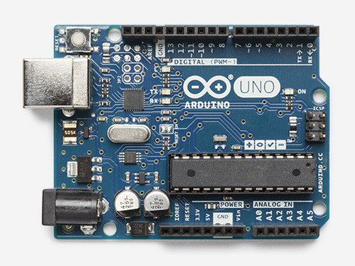
A 35 seconds walk through the Arduino language specifications and how to use it.
By reading the below, in 35 seconds you will have a complete knowledge of the Arduino programming language specifications. Then scroll to the bottom for how to use it.
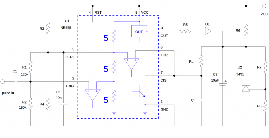
Kiril Karagiozov @ edn.com has a circuit idea that is able to deliver constant power to a load. This is done by generating energy pulses, independent of resistance of the load.
If you have a load with a variable or poorly specified resistance and want to regulate the power applied to it (a heater for example), merely controlling the voltage or current will not work, as in both cases the power P = I2R = V2/R depends on R.
Instead, let us generate pulses with constant energy Epulse, independent of the resistance of the load RL. Then by changing the frequency f of the pulses we can conveniently and precisely control the load power (P = f·Epulse), from 0 to a known maximum level.
Circuit delivers constant power to a load – [Link]
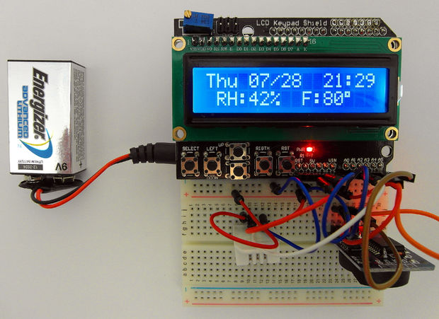
Jordan Kreindler shows us how to build a Battery Saving LCD display that is a able to show Time, Date, Humidity and temperature using DHT22, RTC3231 and Arduino.
The power saving mode here is what sets this Instructable apart from other examples showing day of the week, month, day of the month, time, humidity, and temperature. It is this capability that allows this project to be run from a battery, without the requirement for a “wall wart”.
Calendar- Time – Humidity and Temperature Arduino LCD display – [Link]
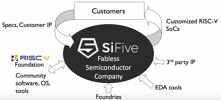
SiFive, a startup from San Francisco, is trying to democratize the access to the world of SoC designing and manufacturing by giving the ability of customizing silicon to the smallest company, inventor, or maker, and taking “the hard parts of building chips working with 3rd part IP, EDA tools and foundries … “ stated by Jack Kang from SiFive.
SiFive is a fabless semiconductor company building customizable SoCs. SiFive takes benefits from using RISC-V in their SoC design. Some of inventors of the open source ISA RISC-V are behind SiFive.
SiFive have an IP called Coreplex, it contains U series and E series. U series contains a high-performance multi-core RISC-V CPUs that can run up to 1.6GHz while E series contains a 32-bit RISC-V CPUs.
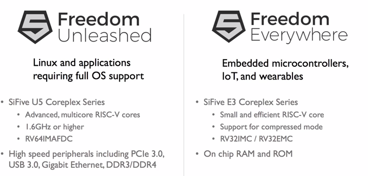
They designed freedom platforms, Unleashed and Everywhere platforms, which are a verified base silicon platforms that allows software development and prototyping and provide the ability to create silicon customization.
Michael Ossmann shared some of his practical experience and insights in designing RF PCBs, Michael designed a lot of RF PCBs like HackRF One, which is an open source SDR (Software Defined Radio) platform.
Michael tips don’t include talking about Smith charts, Q factor, S parameters …etc which need a lot of academic knowledge, instead we will take “the simple way” as he said in his presentation.
The presentation consists of three parts: 5 rules for RF circuit design, some examples from Michael’s boards and how to select the components for the RF circuit design.
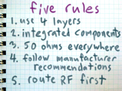
Michael tipped us with his 5 rules for RF circuit design:
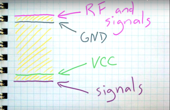
Rule One: Use Four Layers
It’s not obligatory to use 4 layers in RF design, “you can do 2-layer design but you better start reading” Michael said. if you don’t like to do an advanced RF study of your circuit, then use 4-layer design and follow the signal stack below.
Rule Two: Use Integrated Components
Always try to find an integrated component that meets your application. for example, use transceiver ICs like: CC2650, CC1310, ADF7242, AT88RF215, nRF24L01+… etc.
Also use passive components like filters in a shape of integrated component which is much easier than design a discrete one.
Rule Three: Use 50 ohm everywhere
The reason to use 50 ohm is to do impedance matching. This include microstrip impedance calculation to know it’s resistance and Michael showed us how to calculate that using online tools.
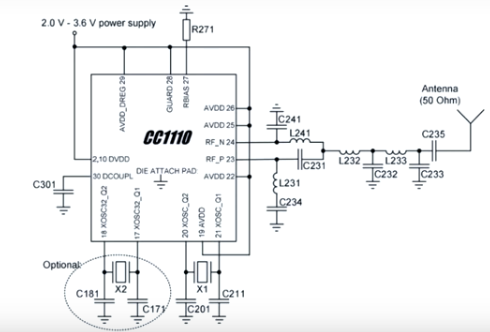
Rule Four: Follow The Manufacturer recommendations
Some times, the manufacturer will provide you with a reference circuit to match the impedance of output to 50 ohms, just follow this circuit!
Rule Five: Route RF First
Keep RF traces short and direct and keep other signals away from RF.
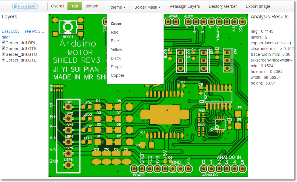
EasyEDA is a cloud-based EDA tool suite which supports open source and working collaboratively. Tools from EasyEDA include circuit simulation using Spice, PCB design, electronic circuit design and now RS-274X (Gerber) and Excellon gerber viewer, all are free. To use this viewer you need to upload your gerber files, in RS-274X format, in a zip file.
EasyEDA’s gerber viewer allows zooming in/out the imported gerber files, choosing the color of PCB, exporting to image, enable/disable view of layers (files) of gerber, sharing the gerber online using the URL after uploading the files and showing some analysis data (Design for Manufacturing DFM) from gerber files like the number of layers, hole and track sizes, clearances and dimension of board.
EasyEDA offers some tutorials/links to learn how to export gerber files for different EDA tools like: Kicad, Altium ,Eagle and Diptrace.
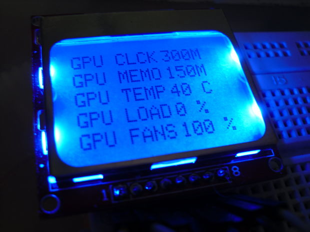
Vincenzopaolo FlameE @ instructables.com shows us how to create an external hardware monitor based on Arduino and Nokia LCD display. Communication with the PC is done using Visual Basic program.
Hi guys! Today I will show you how create an external hardware monitor with any Arduino board(in my case a pro micro board), a Nokia 5110 LCD and some VB programming! Let’s get started!