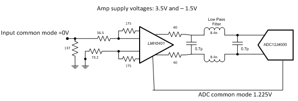
Loren Siebert @ ti.com discuss about how to interface signals that have a reference voltage that isn’t 0V while preserving the DC information.
Many signal paths are direct current (DC)-coupled, and this can lead to challenges when different portions of the signal path require different operating conditions. Many portions of a signal path are ground-referenced, where a signal varies at about an average or mid value of 0V. If all signals had the same reference voltage, DC coupling would be very easy. Unfortunately, that is not the case. Devices operating from a single supply like mixers or analog-to-digital converters (ADCs) will typically have a reference voltage (common mode) that is not 0V. Interfacing these devices while preserving DC information can be challenging.
How to use a fully differential amplifier as a level shifter – [Link]
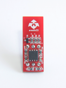
Noela and Miguel from Area0x33 made a really helpful tool on hackaday.io. They designed a fully open source hardware USB stick to store your username/password pairs on.
MemType uses Atmel ATtiny85 MCU and V-USB to do the communication over USB. V-USB is software-only implementation of a low-speed USB device for Atmel’s AVR microcontrollers.
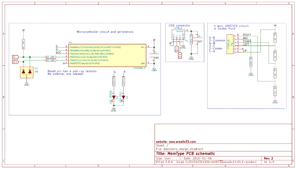
Memtype Schematic
Memtype uses [NOEKEON] to encrypt the stored values with 2K flash reserved for storage, and a PIN number, settable by user, to protect your information if your stick was lost. There is no need for any drivers, because Memtype is numerated as a keyboard. You just need to plug it in usb, enter the PIN code, and then choose your username/password. It uses 5-way tactile switch as user input.
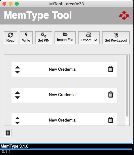
To make things easier, they labeled each username/password with names, and with import and export features supported in .xml form. These features managed by a software tool called MemTypeTool.
You can purchase Memtype from tindie for 24$, and source files are available on Github for both hardware and software.
For more information on how Memtype works, please watch this video below:
When you see some board designs, especially ones with high speed signals or differential pair signals, then you will notice a lot of zigzag/meander lines on PCB.
If you’re wondering whether you can do differential pair routing, then the answer is simply yes by using Meander tool.
First, let’s see how we can draw Differential Pair in Eagle. To do so, follow these steps:
Select two lines, give one of them any descriptive name you want ended with _n and the give the name to the other except that it should be ended with _p.
When you route them, you will notice that trace is drawn for both of them, if you want to trace just one, then you need to press esc.
You can determine the clearance between both of them while drawing by changing clearance value from default class (type “class” in command line).
Now, to use Meander tool, follow these steps:
Select Meander Tool from the left sidebar.
When you click on any route, you will see the length of this route. You will need to select a reference length to measure if you want Menders to match the length. Note that there is
no need to have any special name for these two lines. To select the reference wire click ctrl+left mouse button on the trace. Now hit on any trace with left mouse button and it will be compared to the reference length (a percentage will be shown).
If you failed to draw the Meanders, then try a smaller value of clearance for default class (type “class” in command line).
James Lewis from Kemet has made a presentation to address some of misconceptions about capacitors like how you should de-rate capacitors.
James said that de-rating depends on the chemistry and configuration of a particularly capacitor. So he started by asking a question: Should capacitors be de-rated 50%? And the answer was not a simple true or false. It was: it depends…
James talked about the typical construction of Multilayer Ceramic Capacitor(MLCC), Aluminum Electrolytic(wet one), Tantalum, Polymer Electrolytic and Supercapacitors.
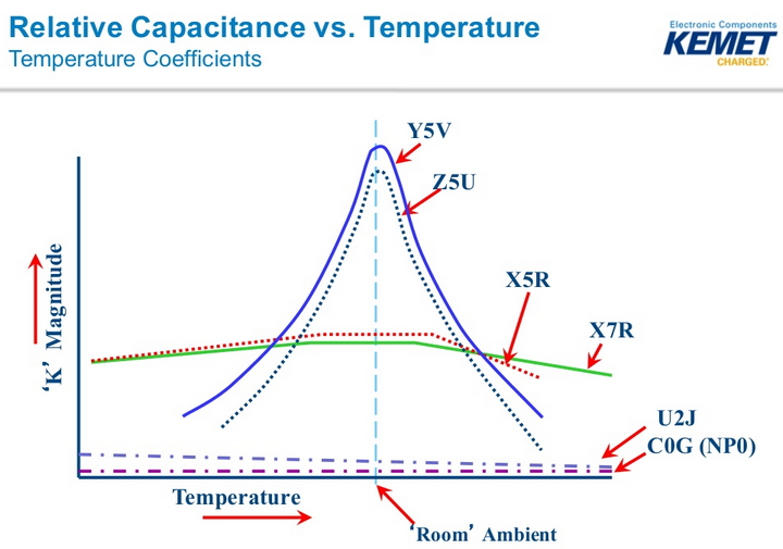
James talked about the Temperature Coefficients diagram for various types of Ceramic Capacitor like: YV, Z5U, X5R, X7R, U2J and C0G [Ceramic Capacitor].
We can see that MLCC capacitance ranges, and Coefficients depend on type.
Another key point was about capacitance change vs DC bias in MLCC. It’s about the role of package size in capacitance lose over DC bias. He compared 10nf and 6.3v rated 1206 package capacitor with same one in 0805 package. Results showed that the 1206 one lost 2% of capacity, while the 0805 lost 50% at 6V. James said that the 0805 package is thinner than the 1206 one, so we need to put more layers into the design to get more capacity. So thinner package leads to worse coefficients.
He pointed out that the capacitance of Wet Aluminum Capacitors is affected on shelves, and he explained how to reform/self-heal them.
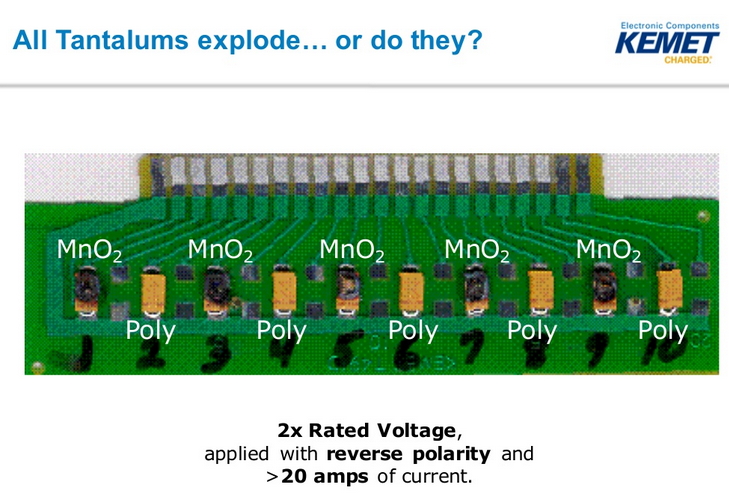
James also explained why it’s safer to use Polymer Electrolytic rather than using Tantalum Capacitors, and why Polymer Electrolytic when fails, it fails safely.
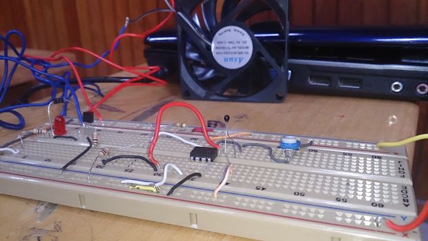
Ahmad Al-Shalabi and Bassma Karbouj show us how to control a DC fan using easy to find components. The fan works when temperature reach into pre-specified threshold.
The purpose of this project is creating a cooling system by controlling in a DC fan in a simple way without using Microcontrollers or Arduino but by using electronic components that it’s very simple and available. The DC fan controlling achieved by a Thermistor and which is a type of resistor whose resistance is dependent on temperature. there is two type of thermistor that is NTC ” Negative Temperature Coefficient” , PTC ” Positive Temperature Coefficient “
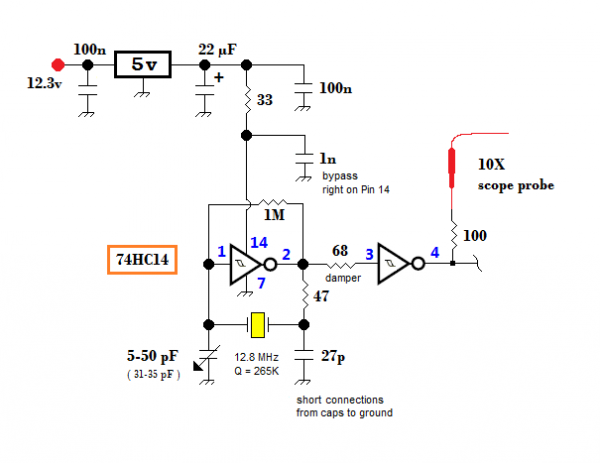
Vasily Ivanenko build some discrete chip oscillators with 74HC series logic gates and tests them on his oscilloscope. He writes:
In numerous RF synthesizer chips lies an inverter with input and output pins for making a reference crystal oscillator clock. I built some discrete chip inverter xtal oscillators with 74HC series logic gates to better examine them. You’ll quickly recognize the oft-used Pierce oscillator topology with 1 trimmer capacitor to tweak the fundamental frequency which might vary from factors like crystal aging and gate, crystal, crystal holder + board reactances. I determined the 27 pF and trimmer cap values through experiments and measures.
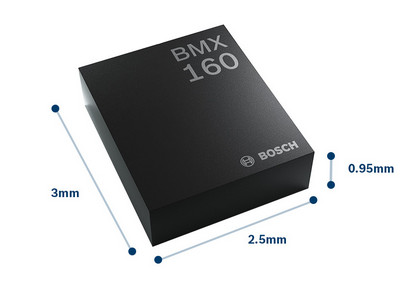
Bosch Sensortec announced a new 9-axis motion sensor, the BMX160, on June 21, 2016. BMX160 targets smartphones, smartwatches and other wearables applications. It has a low power consumption (580 μA), which is proper for long working time on battery for this type of applications, also BMX160 is fully Android Marshmallow compliant.
BMX160 integrates 3-axis accelerometer, gyroscope and geomagnetic. This new sensor comes in 14-pin 2.5 × 3.0 × 0.95 mm³ LGA package and Sensortec claims that it’s the world’s smallest 9-axis motion sensor until now.
BMX160 is fully compatible to BMI160 to easy upgrade your design from the 6-axes measurement unit to the 9-axes one. It has 1024 byte FIFO buffer and a wide VDD voltage range from 1.71V to 3.6V and a VDDIO range from 1.2V to 3.6V.
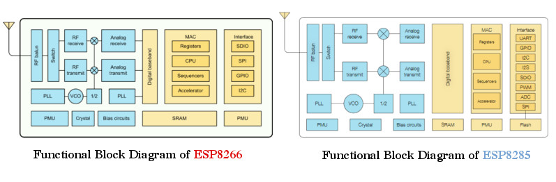
Espressif announced ESP8285 a Wi-Fi chip for wearable devices on May,2016.
Some described this chip as the killer of ESP8266, that is because ESP8285 includes an embedded 1 MByte flash memory. This means smaller area in PCB is needed to include your Wifi chip while the old ESP8266 needed external SPI flash to run user application.
Comparing ESP8266 and ESP8285 Block Diagrams
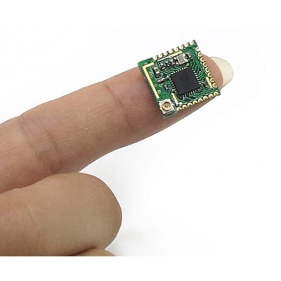
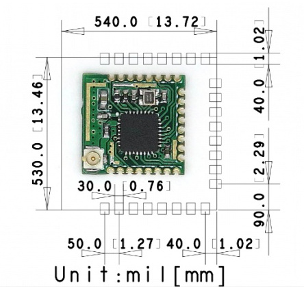
ITEAD announced a new Wifi module called PSF-A85. It adopts the new chip ESP8285 for 1.99$. This module is the first module that adopts ESP8285. PSF-A85 has 24 pin PCB package with a very small footprint: 1.4cm*1.35cm and no embedded antenna on PCB, so this module needs an external antenna through IPEX connector.
You can compare this module with previous ESP-XX modules, also you can see pinout, package details, technical docs, …etc of this module from the ITEAD Studio wiki page.
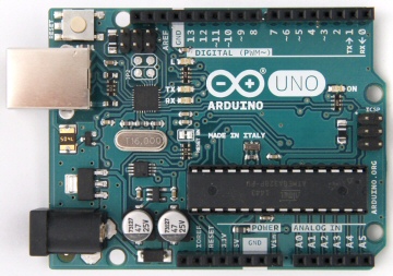
If you’re one of EAGLE CAD fans, and you were wondering how some boards like Arduino boards have what’s called a negative silkscreen, hollow rectangles or shapes by text or logo, then you will learn how to do it with Ishaan’s video tutorial.
Ishaan used a ULP called “negasilk.ulp” in his tutorial. It is written by Christian Bohrer, and it can be downloaded here.
We’ve tested this trick in ElectronicsLab using these steps:
Adding some texts on layer 41tRestrict.
Drawing a rectangular polygon in 1Top layer with width 8 mil (according to Ishaan, this ULP accepts only this width), and don’t forget to hit ratsnest.
Run negasilk.ulp.
A script file is generated in the same directory of your .brd file, open it and make the following modification using any text editor (adding layer 21 line). Set Wire_Bend 2; LAYER 21; GRID MM;
Finally, delete the unwanted polygon and text from layer 41 and layer 1.
You can see these steps in the following GIF(click to view):
Steps to Generate Inverted Silkscreen In Eagle CAD
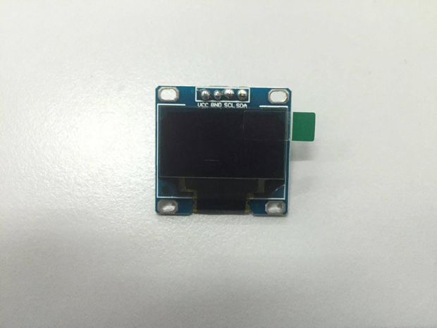
This tutorial is going to teach you the basics on using OLED 0.96inch LCD128x64 with Arduino.
OLED 0.96 inch is a monochrome graphic display module with a built-in 0.96 inch, 128X64 high-resolution display. OLED 0.96inch is able to work despite the absence of backlight. In a dark environment, contrast of OLED display is higher than LCD display. This device is I^2C or SPI compatible. Due to its capability in displaying, it is often used in various application for instances, smart watch, MP3, function cellphone, portable health device and many others.
How to interface OLED 0.96inch LCD with Arduino – [Link]