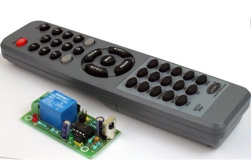
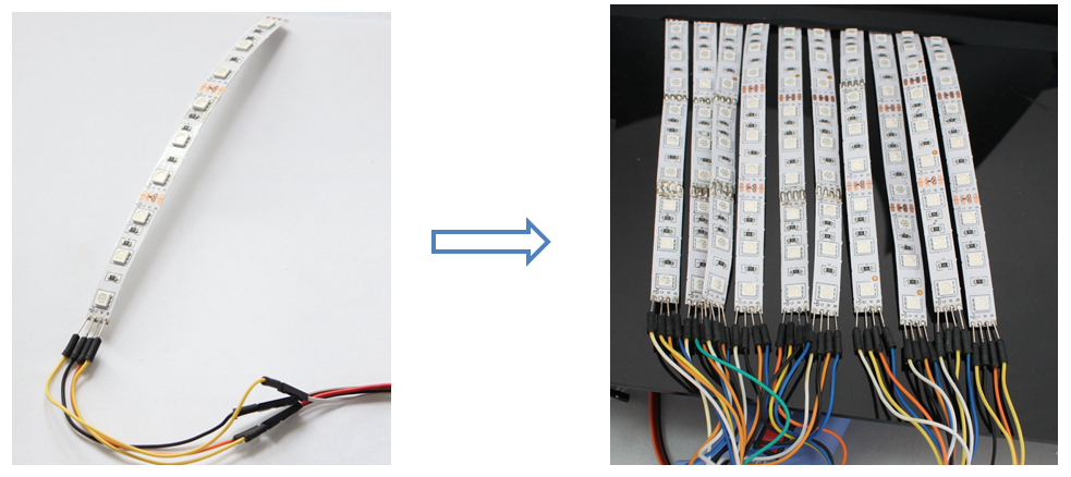
Today I want to make a LED Scroll Bar as is shown in the picture above. Ten LED strips can flash in different effect by using a control board.
Components
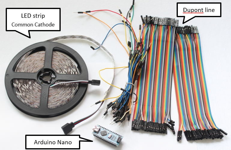
LED strip, Arduino Nano, Dupont line and a control board.
How to make it ?
Step 1)
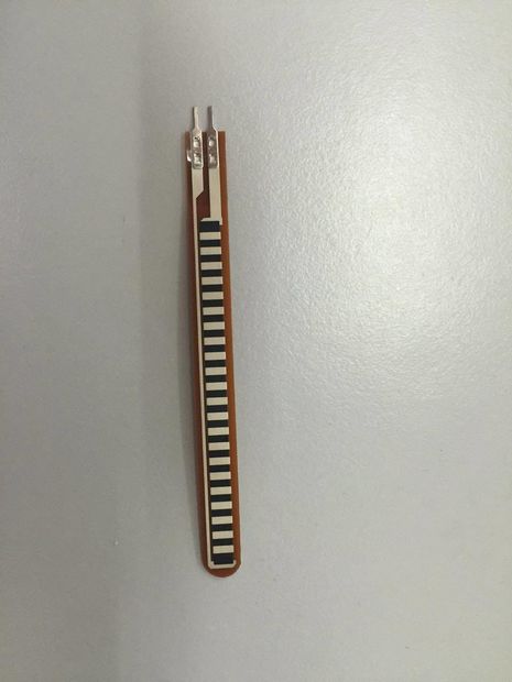
Cut the LED strip into 10 pieces with each LED arbitrary number.
Then, weld the traverse at an interface of the LED strip. Here I prefer using Dupont line to connect.
Step 2) Design
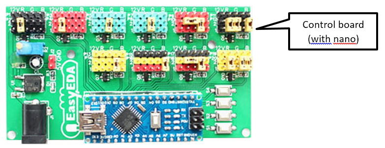
Make a control board. A control board is the pattern to control the flash of the LED strips. Aided by Arduino Nano and equipped with a keypad, we can control the LED strip to display different pattern.
Step 2.1) Design Schematic.
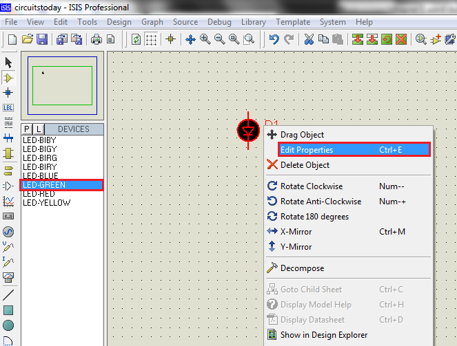
EasyEDA is a free EDA tool suite, it includes Schematic Editor, PCB layout, it has integrated a large number of component libraries, so you can feel easy to find the desired parts.
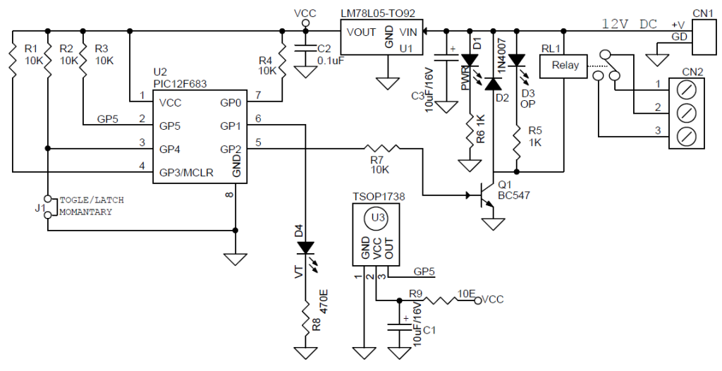
This is my Schematic shown in the picture below.
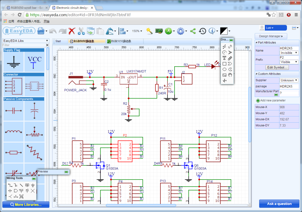
Notes: The voltage of the LED strip is 12 V with Nano 5V. Please remember to add a power regulator such as AMS1117-5.0.
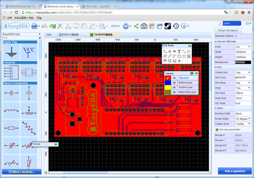
Step 2.2) PCB Layout.
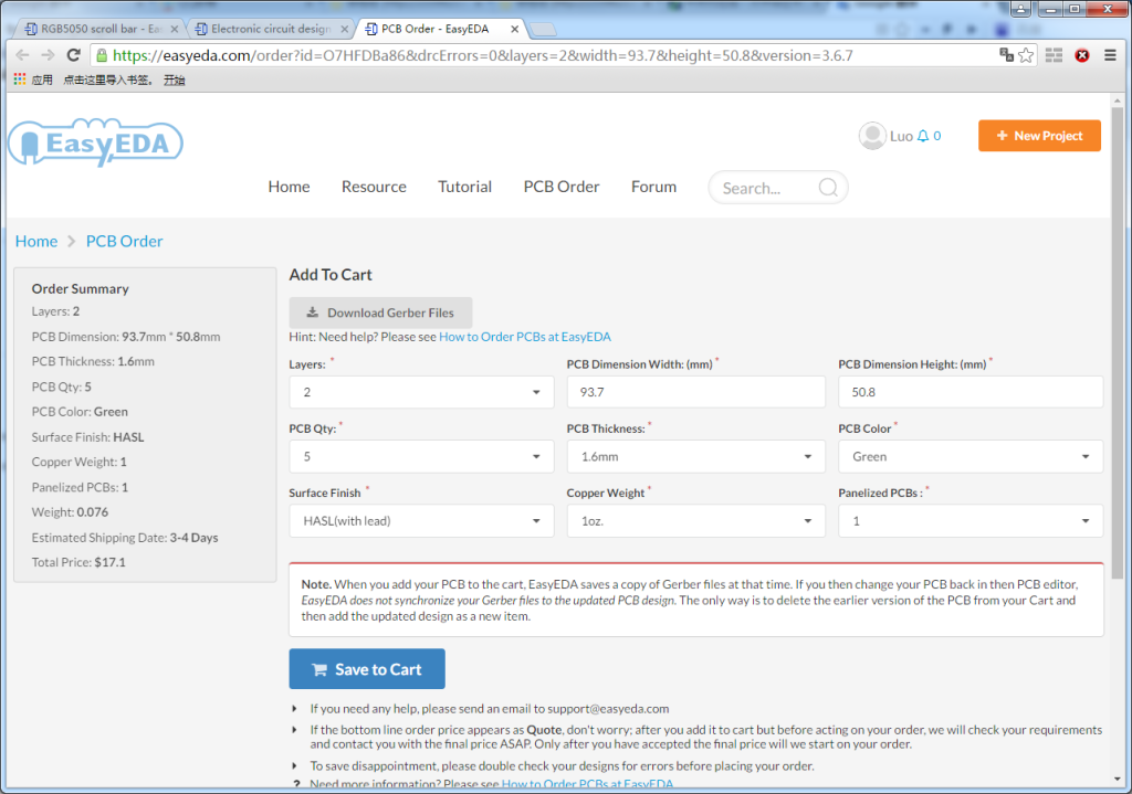
Step 2.3) Make a sample
After finishing designing the PCB, you can click the icon of Fabrication output above. Then you will come into the page of download gerber files and make sample, and are required to fill in some information such as PCB Thickness, Color, Qty of the plate. Next, add it to the shopping cart and after the payment is done, it is finished.
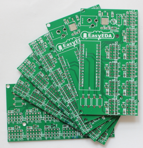
Step 2.4) Take delivery of the PCB
What a good PCB!
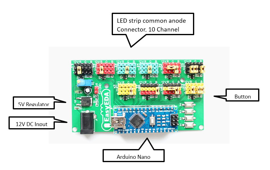
Step 2.5) Welding
It is very easy to make a control board. Just as the following picture described, as soon as the components are welded, it is completed.
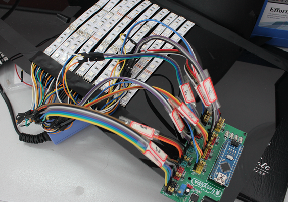
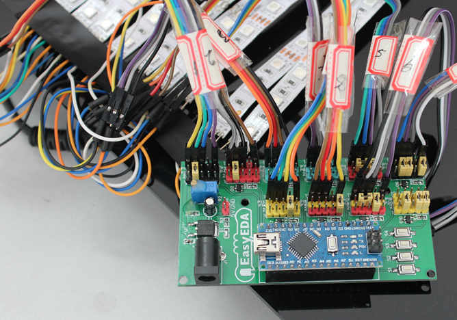
Step 3) Connection
Connect the LED strip into the control board and at the same time please pay attention to the positive and negative of the terminals.
As is shown in the picture below.
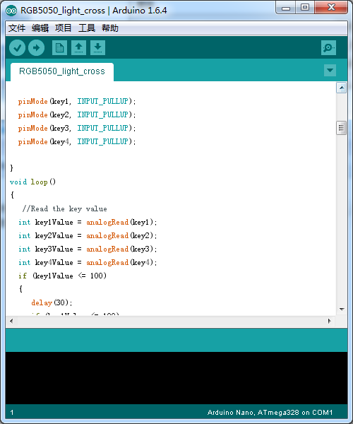
Step 4) Download a program
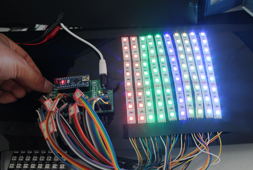
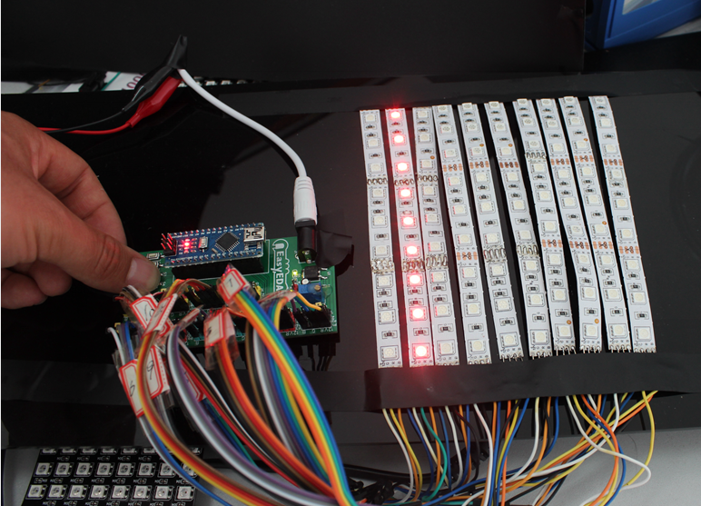
Connect it to a 12 V power supply, download a program on the Arduino Nano and run it.
Press the button to switch flashes.
Here is the program.
Now I have finished my scroll bar.
You can also write a program to make the LED strip flash the way you want it to.
Video