An Introduction to LiPo Batteries

LiPo-Battery-1024x683

Average Man Vs Raspberry Pi has a handy article on LiPo batteries.

LiPo batteries – to fear or not to fear? Up until very recently, I was petrified.

Whilst most other competitors at Pi Wars 2015 were happily using this angry and volatile battery technology, Average Man over here was assuming he was playing it safe using heavy NiMH battery packs in AverageBot.

I was first introduced to LiPo (‘Lithium Polymer’) batteries during my days playing with RC cars. At that time they seemed to have the label of “an advanced new battery technology that needs expert care or they’ll blow your face off“. That was enough to put me off, I’m far too pretty.

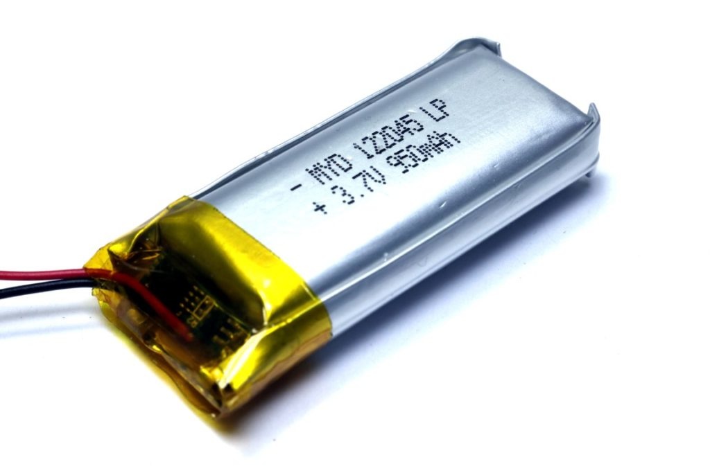
Fast forward many (I won’t say how many) years and LiPo is commonplace –  the world seems to have forgotten how dangerous these little 3.7V packs are – or maybe the technology has improved?

An Introduction to LiPo Batteries – [Link]

Fluke 15B+ Digital Multimeter Upgraded with ESP8266

IMG_0122

SpritesMods has a 5-part write-up that shows how to add wireless connectivity to a Fluke 15B+ digital multimeter

All in all, I feel like I have succesfully diversified my multimeter assortment. I have a Fluke 17B I can use for daily work so I can enjoy quick continuity testing and non-irritating power-off features, and I have the 15B+ as a very capable second multimeter, with WiFi connectivity to show trends and to allow for any device with a browser to act as a remote display. It’s a shame I couldn’t figure out more of the way the main multimeter chip works to get direct access to the display, but the PWM-trick I did to show the IP-address is an alternative that is workable. Here’s a demonstration. As you can see, the multimeter has the IP of 192.168.5.117, and that’s what I enter into the browser.

Fluke 15B+ Digital Multimeter Upgraded with ESP8266 – [Link]

Basics of the I2C Communication Protocol

Introduction-to-I2C-Single-Master-Single-Slave

circuitbasics.com talks about the I2C protocol, it’s use and it’s advantages and disadvantages.

I2C combines the best features of SPI and UARTs. With I2C, you can connect multiple slaves to a single master (like SPI) and you can have multiple masters controlling single, or multiple slaves. This is really useful when you want to have more than one microcontrollers logging data to a single memory card or displaying text to a single LCD.

Basics of the I2C Communication Protocol – [Link]

How to get sensor data from a remote Arduino via Wireless Lora Protocol

FVW4EUDIQ6WTWK3.MEDIUM

by David_Dragino @ instructables.com

This is an example to show how to get sensor data from a remote Arduino via Wireless Lora Protocol.

The exampels requries below hardwares:

1) Client Side: Arduino + Lora Shield (868Mhz) + DS18B20 (Temperature Sensor).

2) Server Side: Arduino + Lora Shield (868Mhz) + Yun Shield + USB flash.

How to get sensor data from a remote Arduino via Wireless Lora Protocol – [Link]

The cheapest ESP8266 programmer!

Esquematico_Sin_Divisor

Gustavo Reynaga shows us how to you can flash your ESP-01 and esp-201 with Arduino IDE and upload any other firmware with ESP flash tools.

Hi folks, now I’ll teach you how to make your programmer to the ESP-01 and ESP-201, (perhaps serve with other models) using an Arduino UNO, a few cables and optionally a button and a slide switch, in my case I use them because I had available, with this programmer able to upload the Arduino sketches and any other firmware (AT, LUA, Espruino, etc).

The cheapest ESP8266 programmer! – [Link]

Basics of the SPI Communication Protocol

Introduction-to-SPI-Multiple-Slave-Configuration-Separate-Slave-Select

circuitbasics.com talks about the SPI serial communications protocol:

One unique benefit of SPI is the fact that data can be transferred without interruption. Any number of bits can be sent or received in a continuous stream. With I2C and UART, data is sent in packets, limited to a specific number of bits. Start and stop conditions define the beginning and end of each packet, so the data is interrupted during transmission.

Basics of the SPI Communication Protocol – [Link]

Understanding Arduino UNO Hardware Design

Arduino_Parts_diag

Yahya Tawil tipped us with his latest article that explains how Arduino works from an electronic design perspective.

Most articles explain the software of Arduinos. However, understanding hardware design helps you to make the next step in the Arduino journey. A good grasp of the electronic design of your Arduino hardware will help you learn how to embed an Arduino in the design of a final product, including what to keep and what to omit from your original design.

Understanding Arduino UNO Hardware Design – [Link]

LTM8003 – 40VIN, 3.5A Step-Down μModule Regulator

160701edne-linear8003

LTM8003 is a step-down DC/DC µModule (micro-module) regulator with a 40V input voltage rating (42V abs. Max.) and 3.5A of continuous (6A peak) output current. The LTM8003’s pinout is FMEA (failure mode effects analysis) compliant, so the output voltage stays at or below the regulation voltage in the event of short-circuit to GND, short-circuit to a neighbouring pin or if a pin is left floating.

The maximum junction temperature of the H-grade version is 150°C, for high temperature or high power automotive and industrial applications. The LTM8003 operates from an input voltage range of 3.4V to 40V and has an adjustable output voltage range of 0.97V to 18V. The switching frequency is adjustable via an external resistor or can be synchronized to an external clock from 200 kHz to 3 MHz. The LTM8003 has four operation modes: Burst Mode operation, pulse skip mode, pulse skip mode with spread spectrum and external synch mode. The quiescent current in Burst Mode operation is 25 µA (max), suiting the LTM8003 for battery operated systems, specifically “keep alive” systems.

LTM8003 – 40VIN, 3.5A Step-Down μModule Regulator – [Link]

TOP PCB Companies