
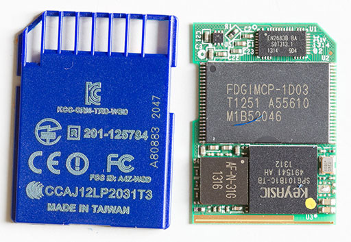
James O’Neill explores a Transcend SD that he believes it’s the smaller Linux server. It’s actually a 16GB memory card, an ARM processor and a WIFI chip all in an SD card package.
The way these cards works is different from the better known Eye-FI card. They are SERVERS : they don’t upload pictures to a service by themselves, instead they expect a client to come to them, discover the files they want and download them. The way we’re expected to do this is using HTTP , either from a web browser or from an App on a mobile device which acts as wrapper for the same HTTP requests.
Exploring the Transcend Wifi-SD card – [Link]

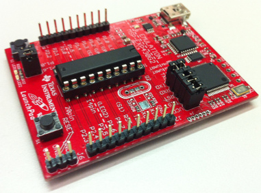
Rahul Sreedharan introduces us to TI’s MSP430 microcontroller using LaunchPad board.
In this tutorial we will be exploring the workings of a MSP430 based microcontroller from Texas Instruments. MSP430 is developed by Texas Instruments as an extremely low power 16 bit architecture for use in low power, low cost, energy constrained embedded applicationsThe Hardware used is the MSP430 Launchpad from TI which contains a programmer/Debugger + two microcontrollers making it an ideal platform to start learning about MSP430G2xxx controller.
An Introduction to MSP430 Launchpad – [Link]

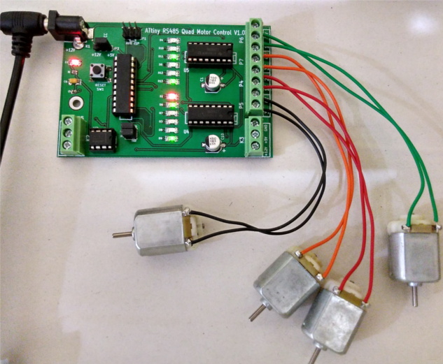
Rahul @ Xanthium has posted a tutorial on interfacing ATtiny with L293D:
In this tutorial we will learn to interface L293D with ATMEL ATtiny microcontroller and control them bidirectionally.The microcontroller used here is ATtiny2313A which is interfaced to two L293D motor control chips for controlling upto 4 DC brushed motors.You can control upto 8 motors if bidirectional control is not needed.
The ability to control upto 4 motors is essential when we are building 4 wheel drive robotic projects like Rovers or under water ROV’s.
ATtiny based bidirectional motor control using L293D – [Link]

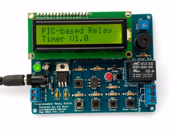
Raj @ embedded-lab.com published a revised version of an old project, a programmable Relay Switch based on PIC16F1847 (or PIC16F628A) that can be used is various automation applications and you can independently set ON and OFF timer with maximum time interval 99 hours and 59 minutes.
Here are the summary of the features that this programmable relay switch has:
- On-board +5V voltage regulator (operates at 9-15V DC input)
- OFF and ON time setup for the relay operation
- Option for cyclic run (maximum 100 cycles, after which the timer stops automatically)
- Stores ON/OFF times and Cyclic option from previous setup into internal EEPROM
- ON/OFF timing range: 0 to 99 hours and 59 minutes with 1 min resolution
- Interactive user interface using 4 tact switches and a character LCD
- On-board buzzer alarm
PIC Programmable Relay Switch – [Link]

by Susan Nordyk @ edn.com:
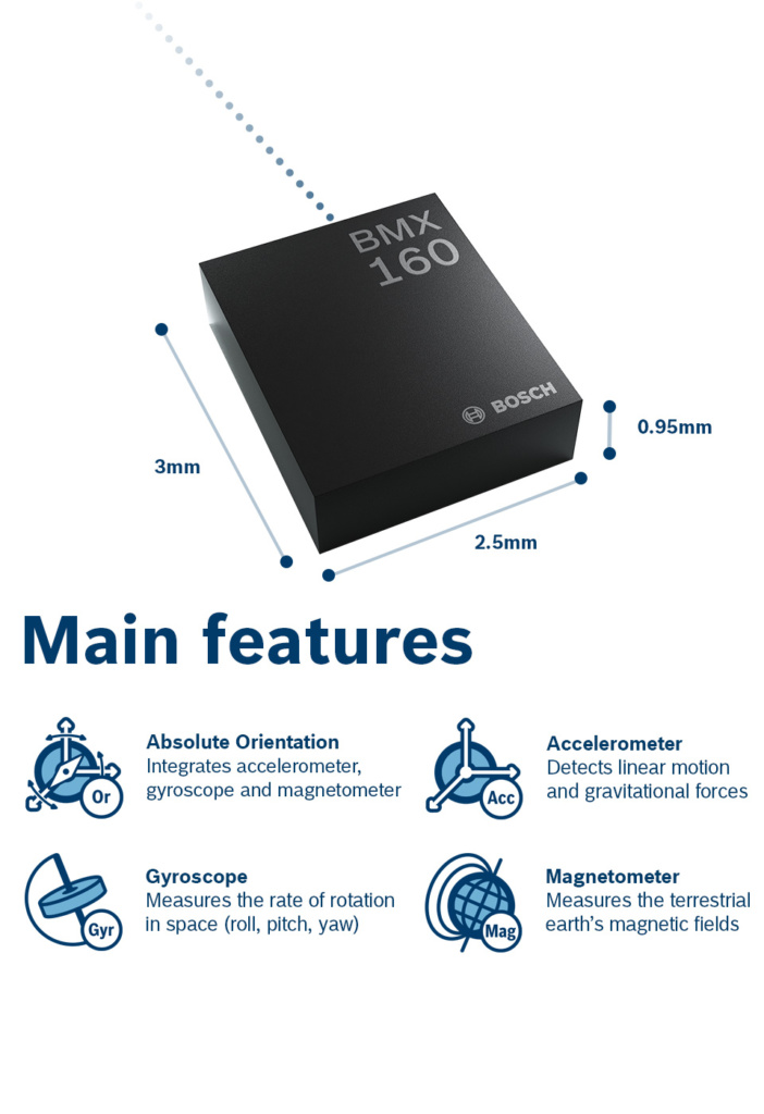
Bosch Sensortec’s BMX160 is a 9-axis motion sensor touted as the smallest in the industry for wearable and augmented/virtual-reality devices. The miniature device is housed in a 2.5×3.0×0.95-mm, 14-pin LGA package, small enough for smartphones, smart watches, fitness trackers, and even smart eyewear and jewelry.
Combining an accelerometer, gyroscope, and geomagnetic sensor, the BMX160 meets the increasingly more stringent low-power requirements required by wearable devices. The BMX160 reduces power consumption to below 1.5 mA and effectively replaces the mainstream two-component design, which employs a 6-axis inertial measurement unit and a 3-axis geomagnetic sensor.
Tiny motion sensor fits wearable devices – [Link]
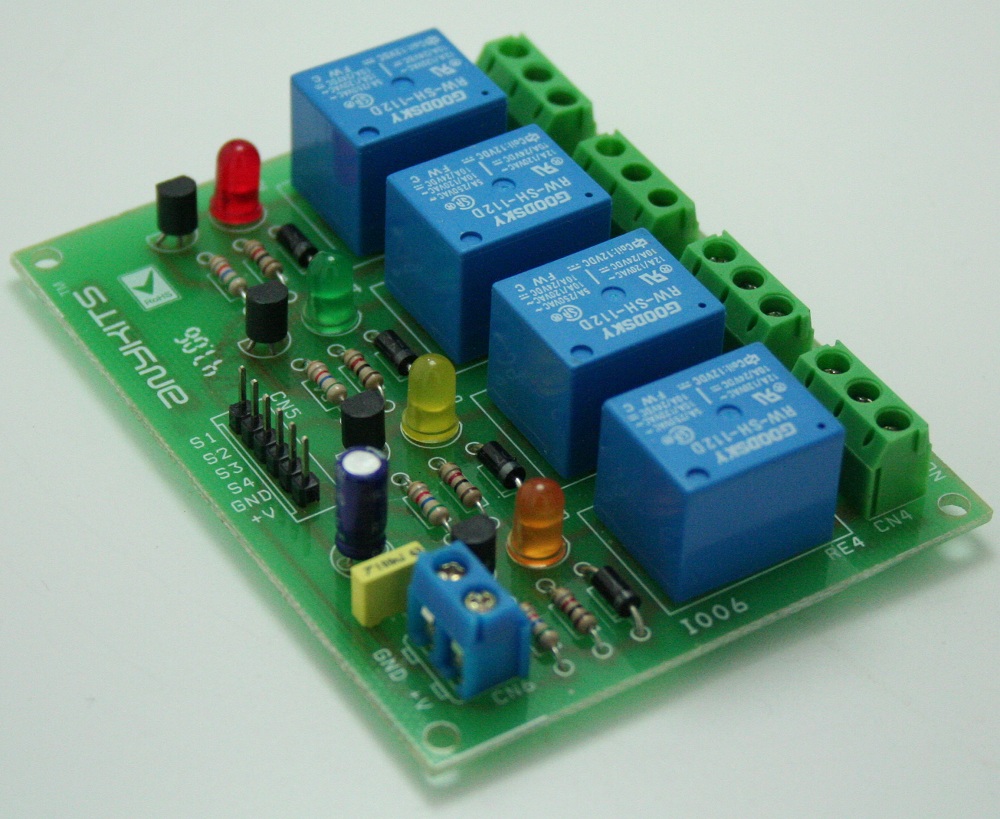
Quad Channel Relay Board is a simple and convenient way to interface 4 relays for switching application in your project.
Features
- Input supply 12 VDC @ 170 mA
- Output four SPDT relay
- Relay specification 5 A @ 230 VAC
- Trigger level 2 ~ 5 VDC
- Berg pins for connecting power and trigger voltage
- LED on each channel indicates relay status
- Power Battery Terminal (PBT) for easy relay output and aux power connection
- Four mounting holes of 3.2 mm each
- PCB dimensions 88 mm x 68 mm
4 Channel Relay Board – [Link]

Quad Channel Relay Board is a simple and convenient way to interface 4 relays for switching application in your project.
Features
- Input supply 12 VDC @ 170 mA
- Output four SPDT relay
- Relay specification 5 A @ 230 VAC
- Trigger level 2 ~ 5 VDC
- Berg pins for connecting power and trigger voltage
- LED on each channel indicates relay status
- Power Battery Terminal (PBT) for easy relay output and aux power connection
- Four mounting holes of 3.2 mm each
- PCB dimensions 88 mm x 68 mm
Applications: Robotics, Electronics projects, Industrial controls, Microwaves Oven, Fans, DC Motor, AC Lamp, Solenoids Remote Controls etc.
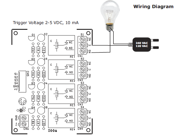
Relay Load (Contact Capacity of Relay)
- 7 A @ 230-250 VAC
- 10 A @ 120 VAC
- 10 A @ 24 VDC
- CN1 – CN4 Connector : Relay 1 to 4 (S1 to S4) Output (Normally Open/Normally Close)
- CN5 Connector : Control Signal Input, Trigger 2 to 5 VDC and Supply Input 12 VDC
- D2,D4,D6,D8 : Relay On/Off LED Indication
- CN6 Connector : Axillary Supply 12 VDC
Schematic

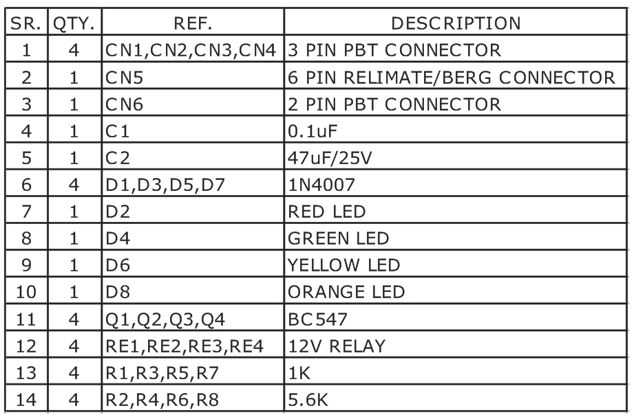
Parts List
Connection

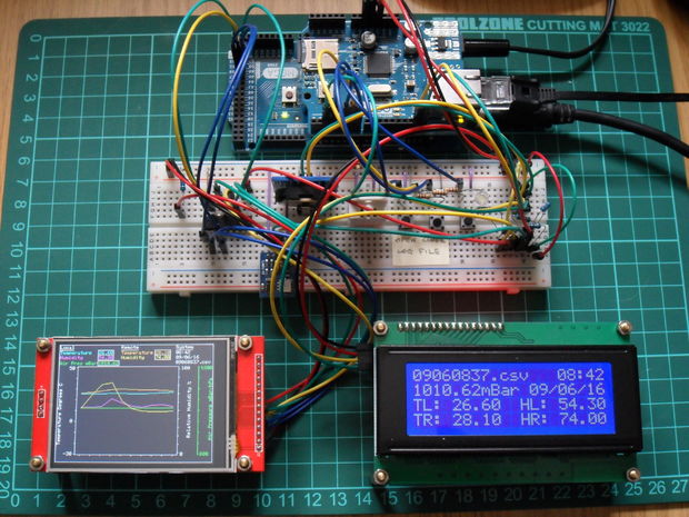
In this series of tutorials SteveQuinn show us how easy is to build a IoT Ethernet Device using ESP8266-01 WiFi module and how interface BMP085 barometric sensor, DS1307Z RTC, ILI9431 and log the data on a SD card.
As mentioned, this Instructable is split into two parts. Part (A) documents how relatively simple it is to cross port to Ethernet, extend and further develop an MQTT IoT device based around the ESP8266-01 WiFi enabled module from the earlier Instructable ‘Pimping your first IoT WiFi Device. Part 4 : IoT, Home Automation’
Creating your first IoT Ethernet Device – IoT, Home Automation – [Link]

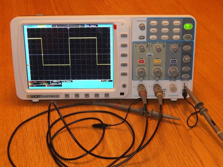
Christer Weinigel did a teardown of OWON SDS7102 oscilloscope. He explained how its internals are connected, ported Linux to its Samsung SoC in the scope, succeeded in getting its peripherals working, and set to work programming the Xilinx FPGA that’s responsible for signal processing.
One of the reasons I bought this specific scope was that I had seen some teardowns of it and knew that the scope has a Samsung System-on-Chip (SoC) and a Spartan 6 FPGA in it and I have some familiarity with both. At the back of my head I had the idea that I might be able to reverse engineer the scope and do something interesting with it.
Hacking the OWON SDS7102 Scope – [Link]

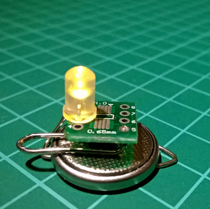
A self-igniting candle implemented using AVR and PIC microcontrollers.
This project has two variations, one using an ATTiny25, the other using a PIC12LF1822.
In a series of minimalistic devices, this electronic candle periodically measures ambient light levels. Once it detects nightfall, it self-ignites and burns for three hours, flickering as a candle does. The flicker intensity changes about every minute, adding more variability.
AVR vs PIC: The case of the candle – [Link]
