Micro-supercapacitor fits inside IoT chips

20160613095602_led-vtt-micro-supercapacitor

by Jan Buiting @ elektormagazine.com:

Zero-power autonomous devices will abound on the IoT of the future, and battery manufacturers are scratching their heads to come up with the best possible solution ensuring high energy and power density at miniature scale. A new material developed recently at Finland-based VTT shows promise, based on energy and power density of a supercapacitor depending on the surface area and conductivity of the solid electrodes. The size? So small it fits inside an IC.

Micro-supercapacitor fits inside IoT chips – [Link]

Bargraph Current Meter 0-1A Range – PIC16F686

BAR-GRAPH-CURRENT-METER-IMG02

Tiny Bar-Graph current meter displays a Red color bright, easy to read display of current range from 0 to 1A.  This Bar-Graph has 20 segments in single color and display 0 to 1Amp Current. The Barograph current monitor is based on PIC microcontroller with 10 Bit resolution ADC.  This high performance measurement provides unique capabilities and can be used in various applications. The Bargraph can display 0 to 1Amp with 20 LED with 50mA (Approx.) resolutions.  Each LED output provided with Solder- jumper for output set point can be configured for control, alarm, Relay Trigger, ideal solution to check the DC Motor current. It is mainly used to measure low side current.

Features

  • Supply 7.5 V to 18V DC (Direct 5V Input Possible)
  • Input 0 to 1Amps across onboard shunt resistor (Max Load supply 48V)
  • Output Display 20 Color RED SMD LEDs
  • Compact Board with SMD Components
  • Supply input Header Connecter
  • On Board 5V Regulator
  • Solder Jumper on each LED for Output Control, Alarm, and Relay

Bargraph Current Meter 0-1A Range – PIC16F686 – [Link]

Bargraph Current Meter 0-1A Range – PIC16F686

BAR-GRAPH-CURRENT-METER-IMG01

Tiny Bar-Graph current meter displays a Red color bright, easy to read display of current range from 0 to 1A.  This Bar-Graph has 20 segments in single color and display 0 to 1Amp Current. The Barograph current monitor is based on PIC microcontroller with 10 Bit resolution ADC.  This high performance measurement provides unique capabilities and can be used in various applications. The Bargraph can display 0 to 1Amp with 20 LED with 50mA (Approx.) resolutions.  Each LED output provided with Solder- jumper for output set point can be configured for control, alarm, Relay Trigger, ideal solution to check the DC Motor current. It is mainly used to measure low side current.

Features

  • Supply 7.5 V to 18V DC (Direct 5V Input Possible)
  • Input 0 to 1Amps across onboard shunt resistor (Max Load supply 48V)
  • Output Display 20 Color RED SMD LEDs
  • Compact Board with SMD Components
  • Supply input Header Connecter
  • On Board 5V Regulator
  • Solder Jumper on each LED for Output Control, Alarm, and Relay

Schematic

BAR-GRAPH-CURRENT-METER-sch

Parts List

BAR-GRAPH-CURRENT-METER-BOM

Wiring

BAR-GRAPH-CURRENT-METER-WIRING

Photos

BAR-GRAPH-CURRENT-METER-IMG02

Video

Electromagnetic Field Detector using an Arduino

FG4OXMYIPH0IJQW.MEDIUM

by LightBug @ instructables.com:

In today’s instructable I’m going to show you how to build your own electromagnetic field meter using an Arduino. This device can be used to detect mains voltage, static electricity and radiations from certain devices.

Electromagnetic Field Detector using an Arduino – [Link]

Elektor GREEN Membership @ 50% OFF – exclusive for Elab visitors

elektor-en-10-2014

Elektor is more than a magazine, it is a community of active electronic engineers eager to learn, make, design and share surprising electronics. If you would like to join this community by purchasing a yearly membership you may consider this exclusive offer. Elektor, offers 50% discount on yearly membership on all electronics-lab.com visitors. To benefit from the offer just enter E-LAB16 code on this form. The offer is valid for Elektor GREEN Membership and costs US $37.50 (€34.00 / £24.48) for a year.

What you get: 

  • 6 Editions of Elektor Magazine (132 pages each) in PDF format
  • Free access to all PDF editions of Elektor Business Magazine (approx. 6 per year)
  • Unrestricted access to the Elektor 2000 – present day archive (thousands of articles!)
  • Full access to over 750 Elektor Labs projects
  • A minimum of 10% discount on all products at Elektor.com

Benefit now!
Enter coupon code E-LAB16 on this page and join the Elektor Community at a special low price!

Intro to Printed Circuit Boards

F62NJ55IPH0FRR8.MEDIUM

This is an intriduconary article about PCBs and their uses.

In this instructable, I’ll go over what a printed circuit board is, where they are used, and the basics of how to make one yourself. So sit back, strap in, and enjoy learning about this very important and interesting method of making electronics!

Intro to Printed Circuit Boards – [Link]

DIY 1GHz Active Probe For Under 20$

FIP1LQ3IP9RCL3V.MEDIUM

thirschbuechler @ instructables.com shows us how to build a 1GHz active probe using BF998 dual-gate MOSFET and some other RF components.

This Instructable will show you how to build a 1GHz* Fet-based Active Probe, the Fetprobe, for about 10$*, provided you have access to an electronics lab. It is based on an Elektor-magazine article (see the pdf’s addendum, section literature in my thesis) beside some other designs. However, as topic of my bachelor-thesis I wanted to find out how good these designs really are and how far one can push them.

DIY 1GHz Active Probe For Under 20$ – [Link]

LTC3895 – Step-down controller handles 150 V

3895Col1
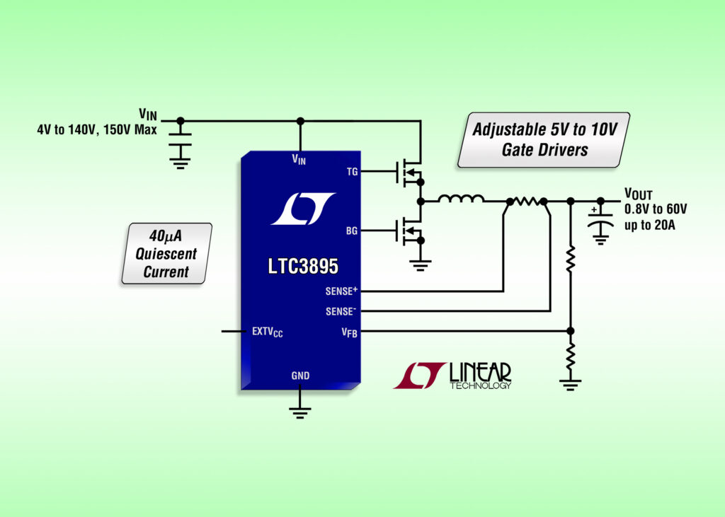
Linear Technology Corporation announces the LTC3895 , a high voltage non-isolated synchronous step-down switching regulator controller that drives an all N-channel MOSFET power stage. Its 4V to 140V (150V abs max) input voltage range is designed to operate from a high input voltage source or from an input that has high voltage surges, eliminating the need for external surge suppression devices. The LTC3895 continues to operate at up to 100% duty cycle during input voltage dips down to 4V, making it well suited for transportation, industrial control, robotic and datacom applications.
The output voltage can be set from 0.8V to 60V at output currents up to 20amps with efficiencies as high as 96%. This part draws only 40μA in sleep mode with the output voltage in regulation, ideal for always-on systems. An internal charge pump allows for 100% duty cycle operation in dropout, a useful feature when powered from a battery during discharge. The
LTC3895’s powerful 1Ω N-channel MOSFET gate drivers can be adjusted from 5V to 10V to enable the use of logic- or standard-level MOSFETs to maximize efficiency. To prevent high on-
chip power dissipation in high input voltage applications, the LTC3895 includes an NDRV pin which drives the gate of an optional external N-channel MOSFET acting as a low dropout linear
regulator to supply IC power. The EXT VCC pin permits the LTC3895 to be powered from the output of the switching regulator or other available source, reducing power dissipation and improving efficiency.
LTC3895 – Step-down controller handles 150 V – [Link]

Pressure, temperature and humidity sensor board with RS485

rhtp-pcbfoto

Mare shares his sensor board based on MS5637 HDC108. He writes:

This is another small module to measure air pressure, temperature and humidity. Two sensors are on-board: MS5637 and HDC1080. Microcontroller is small cortex M0 in TSSOP-20 housing from STM: STM32F070CxP. The SN65HVD72DGKR provides RS485 interface functionality with half duplex mode. Voltage regulator, reverse polarity protection and some LED indicators are provided on-board. Complete module is 10x55mm, produced on single-sided PCB, easily producible in every home lab with proto-PCB capability.

Pressure, temperature and humidity sensor board with RS485 – [Link]

Project curve tracer – progress update

curve-tracer-layout-1v0-official

Jason Jones has been working on a curve tracer project and shows us his June progress:

As the hardware is at the point of initial release, but the firmware and GUI aren’t quite there yet, I decided that it would be prudent to split off the firmware and GUI components into their own GIT repositories. Tracking all files in the same repository was convenient through the initial stages of project development, but splitting them allows for more targeted releases and will likely make contributions easier. For instance, if someone wished to write a Java client, then they could simply fork the GUI repository and not worry about the hardware and firmware repositories.

Project curve tracer – progress update – [Link]

TOP PCB Companies