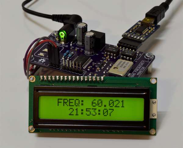
This is the second in a series of posts about designing a mains frequency monitor using the Microchip PIC 16F1619 microcontroller. In this post we will take a look at the first revision of the board that I designed for the project and some of the features that it adds. Be sure to read Part 1 of the project write-up if you haven’t done so already.
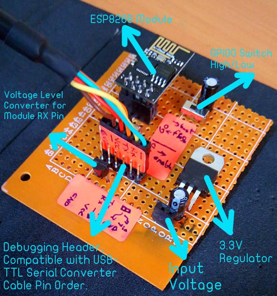
In this article, you’ll learn how to build a system that can turn DC loads on and off using a mobile application. You’ll also learn how to perform this task via immediate actions or via timers set in advance for switching loads on and off. by Yahya Tawil
You can implement this system in environments where you need to set your DC load for a specific time. This will allow you to use our Android application without any need for a hardware interface, keypad, and LCD screen.
How to Build a Control Circuit with Adjustable Working Time via Wi-Fi – [Link]
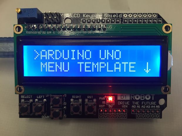
PaulSS @ instructables.com shows us how to build a menu for a LCD/button shield:
While working on a new Instructable (coming soon) I had decided to use an Arduino Uno with an LCD/button shield I purchased off of AliExpress. It’s a knockoff of the DFRobot Shield. I knew that I needed a menu for my project but was becoming so disillusioned with the terrible menu template programs available for the Arduino Uno. Many of which were not designed to work with this shield. I decided to make my own.
A few months ago, with version 1.6.6, the Arduino IDE introduced a great new feature. It is called Serial Plotter and you can find it in your Arduino IDE under the tools menu. Using the Serial Plotter we can graph the output of our Arduino project in real time. A tutorial describing this feature and giving some examples is here.
The Serial Plotter is a software utility that takes incoming serial values over the USB and graphs them against an X/Y axis. The vertical Y axis auto adjusts as the value of the output increases or decreases. The X axis is not time, but each tick on it is equal to an executed serial println command. In simpler words, each time a Serial.println command is executed a new point is added in the graph. Unfortunately we cannot have a graph with more than 500 points but I hope that in a future version of the Arduino IDE, we will be able to have more points.
Arduino Tutorial: Serial Plotter the new impressive tool of the Arduino IDE – [Link]
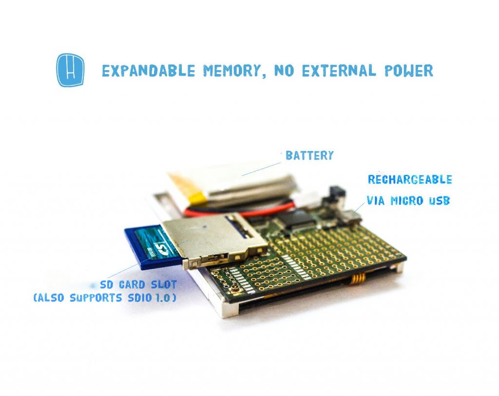
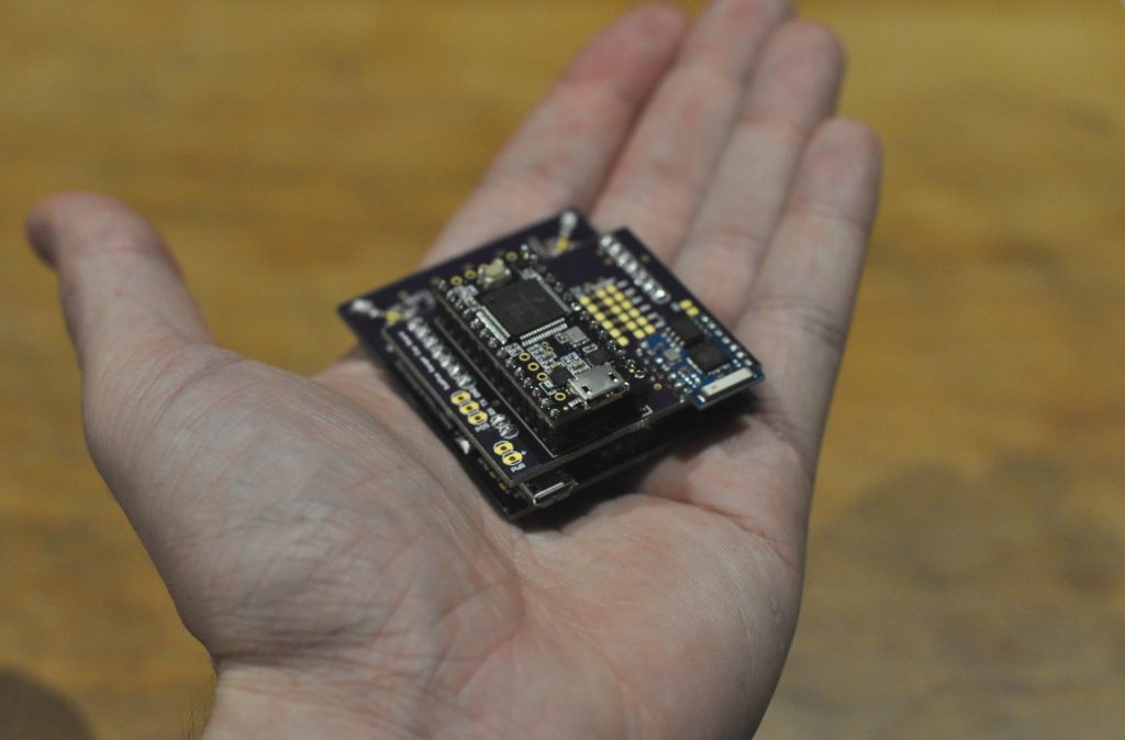
HackPOD is a fast and powerful electronics development platform in a portable smartphone form factor. It is based on a 32-bit ARM Cortex-M4 chip running at a clock speed of 72 MHz and is programmable by the Arduino IDE and C language. It also features an integrated touchscreen LCD, in-built protoboard and SMT space, expandable memory , and a rechargeable battery.
HackPOD – 32 bit ARM Cortex-M4, programmable in Arduino – [Link]
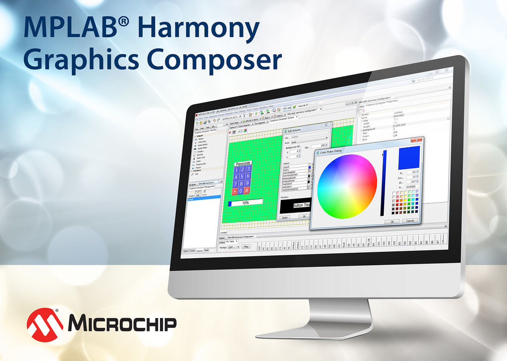
Microchip Technology Inc. (NASDAQ: MCHP), a leading provider of microcontroller, mixed-signal, analog and Flash-IP solutions, today announced the MPLAB® Harmony Graphics Composer (MHGC), a modern and flexible graphical user interface (GUI) composer tool. MHGC is a free development tool for developing GUIs for all PIC32 microcontrollers through Microchip’s Harmony Configurator and MPLAB X Integrated Development Environment (IDE). The software allows anyone to create branded content using the Harmony Graphics Library, in conjunction with their custom assets, to create GUIs in a What-You-See-is-What-You-Get (WYSIWYG) design model, without complex and cumbersome coding.
Microchip announced MPLAB® Harmony Graphics Composer GUI Tool – [Link]
SubPos Positioning System – A “dataless” Wi-Fi positioning system that can be used anywhere GPS can’t.
SubPos is an indoor positioning system that can be used in various environments such as metro lines, shopping malls, carparks, art galleries or even conference centers; essentially anywhere GPS doesn’t penetrate. It could also be integrated into an array of IoT enabled devices, from access points to Wi-Fi enabled light-bulbs.
When the world’s lifeforms are forced into subterranean dwellings due to nuclear fallout, evolution into lizard people or warming of the Earth, we will require a simple method for determining our position underground. In our current age, we are still working out the intricacies associated with determining our location in areas where GPS cannot reach
SubPos: a WiFi Positioning Solution for Places GPS Can’t Reach – [Link]
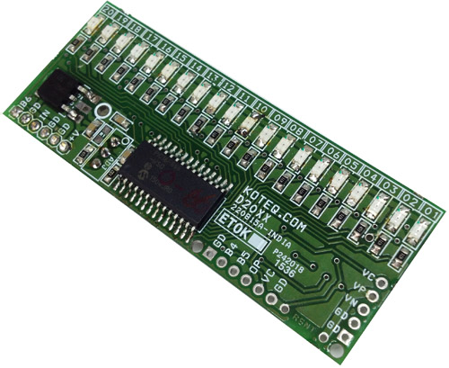
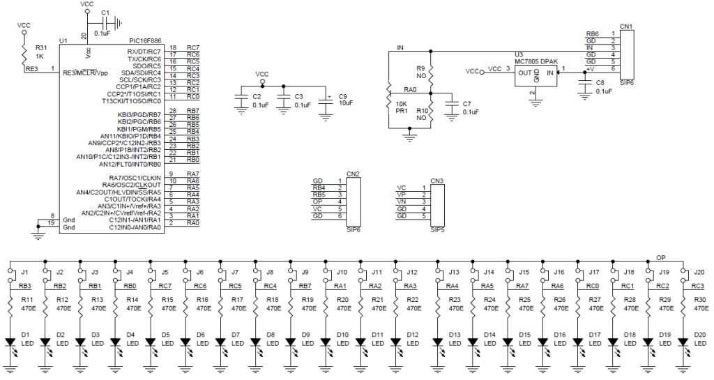
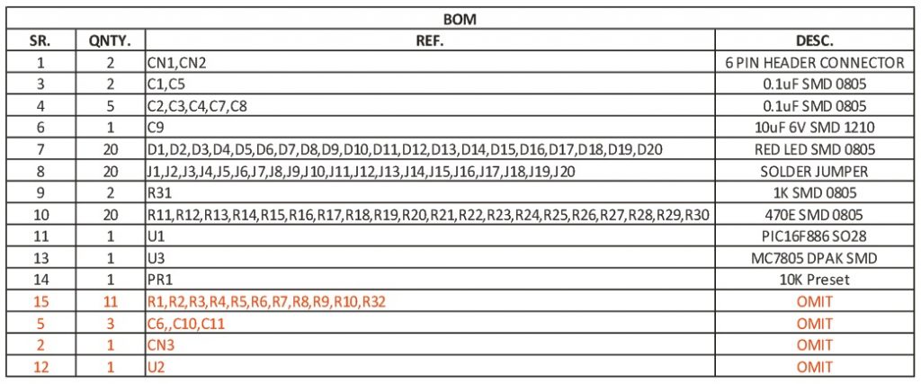
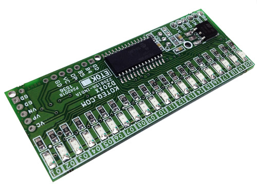
Tiny Bar-Graph displays provide a Red color bright, easy to read display of Voltage range of 0 to 5V. This Bar-Graph has 20 segments in single color and display 0 to 5V DC. The Barograph Voltage monitor is based on PIC microcontroller with 10 Bit resolution ADC. This high performance measurement provides unique capabilities and can be used in various applications. The Bar can display 0 to 5V with 20 LED with 0.25V (Approx.) resolutions. Each LED output provided with Solder- jumper for output set point can be configured for control, alarm, Relay.
Features
Supply 7.5 V to 18V DC (Direct 5V Input Possible)
Test Voltage Input 0 to 5V
Output Display 20 Color RED SMD LEDs
Compact Board with SMD Components
Supply input Header Connecter
On Board 5V Regulator
Resolution 0.25V Approx.
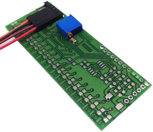
Onboard Trimport to Calibrate The Display Range.
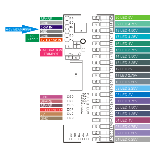
Solder Jumper on each LED for Output Control, Alarm, and Relay
PCB Dimensions 75.88 X 26.69 MM
Bargraph Voltmeter 0-5V DC range – PIC16F686 – [Link]
Tiny Bar-Graph displays provide a Red color bright, easy to read display of Voltage range of 0 to 5V. This Bar-Graph has 20 segments in single color and display 0 to 5V DC. The Barograph Voltage monitor is based on PIC microcontroller with 10 Bit resolution ADC. This high performance measurement provides unique capabilities and can be used in various applications. The Bar can display 0 to 5V with 20 LED with 0.25V (Approx.) resolutions. Each LED output provided with Solder- jumper for output set point can be configured for control, alarm, Relay.
Features
Supply 7.5 V to 18V DC (Direct 5V Input Possible)
Test Voltage Input 0 to 5V
Output Display 20 Color RED SMD LEDs
Compact Board with SMD Components
Supply input Header Connecter
On Board 5V Regulator
Resolution 0.25V Approx.
Onboard Trimport to Calibrate The Display Range.
Solder Jumper on each LED for Output Control, Alarm, and Relay
PCB Dimensions 75.88 X 26.69 MM
Calibration: Apply 7V to 18V DC supply, Apply accurate 5V at Input pin, Turn PR1 Trimport CCW/CW so all LED glow.