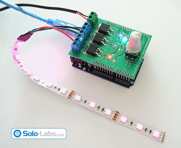
One of our visitors tipped us with his latest project, an Arduino RGB LED controller using low Rds-on MOSFETS, designed in Solo-PCB.
This Arduino shield is designed to drive RGB (Red Green Blue) LED strips by using PWM (Pulse Width Modulation) method. It can brighten up and down each color independently by changing the duty cycle of PWM.You can produce any color by mixing the different percentage of colors. The endless turn rotary encoder on the board allows the user select the channel and change its brightness. Low Rds-on resistance MOSFETs, which are the switching elements, generate very low heat dissipation even used with large number of LEDs.
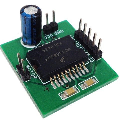
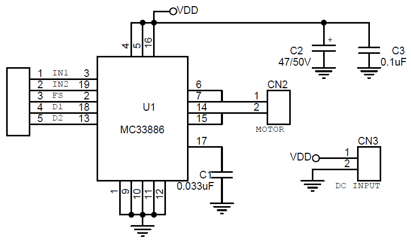
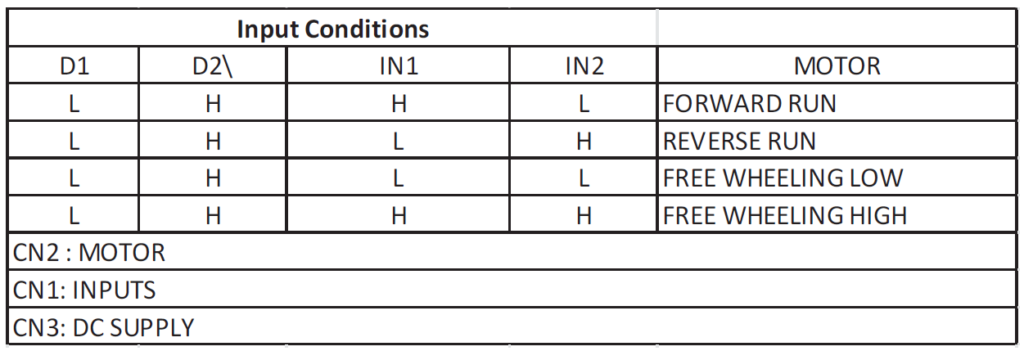
This tiny module has been designed to be used in Robotics, Power tools, automotive applications etc. The module is based on MC33886 from NXP. The MC33886 is a monolithic power IC comprising control logic, charge pump, gate drive, and low RDS(ON)MOSFET, H-Bridge output circuitry in a small surface-mount package. MC33886 is a monolithic H-Bridge ideal for fractional horsepower DC-Motor and bi-directional thrust solenoid control. The IC incorporates internal control logic, charge pump, gate drive, and low Rds. MOSFET output circuitry. The MC33886 is able to control continuous inductive DC load currents up to 5A. Output loads can be pulse-width modulated (PWM) at frequencies up to 10 KHz. A Fault status output reports under-voltage, short-circuit, and over-temperature conditions. Two independent inputs control the two half-bridge totem-pole outputs.
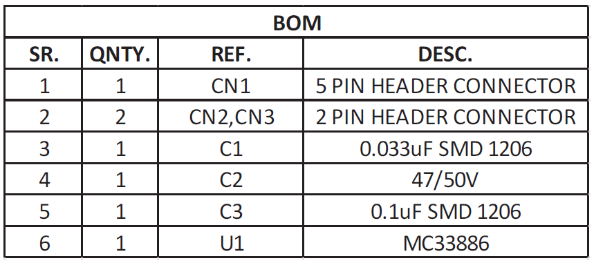
Features
Supply 5V to 28V
TTL/CMOS compatible Inputs
Continuous DC Load Current up to 5.2A min
Output Current Limitation at min. 5.2A with PWM Current Regulation
Short-Circuit Shutdown for Output Currents over 8A
Logic Inputs TTL/CMOS Compatible
Operating Frequency up to 10 kHz
Over temperature and Short Circuit Protections
Under voltage disable Function
Output control via two independent inputs (forward, reverse, free-wheeling low/high)
Two disable inputs are provided: Low =True and High =True
Applications
DC Motor control in Robotics and industrial
DC Motor & actuator control in Recreational Vehicles
In this video we are going to learn how to build our own voltmeter using a very inexpensive sensor. The voltage we measure is then displayed in a Nokia 5110 LCD display. This project is very easy to build and great learning experience.
With this project we can measure the voltage of our voltage sources, or monitor the battery level of our projects. Let’s see the project in action. I have connected two wires to the voltage sensor module I am using today. I place the red wire to the positive terminal of an AA battery and the black wire to the negative terminal of the battery. In the display we get its voltage. Let’s now try this 18650 battery, we get 3.6V. Let’s now measure this big 12V battery. The voltage is 12.2V. If we compare the readings with a Multimeter, we can see that the measurements are really close! The project is working fine. But be careful, the maximum input voltage that this sensor can measure is 25V, so if you exceed it, you are going to burn your Arduino Pin. Let’s now see how to build this project.
DIY Voltmeter using a simple voltage sensor and Arduino Uno and a Nokia 5110 LCD – [Link]
Fluke 279 FC True-rms Thermal Multimeter helps you find, repair, validate, and report many electrical issues quickly so that you are confident problems are solved.
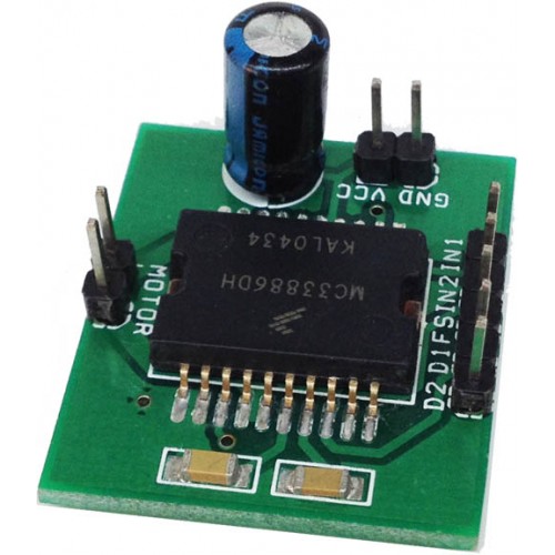
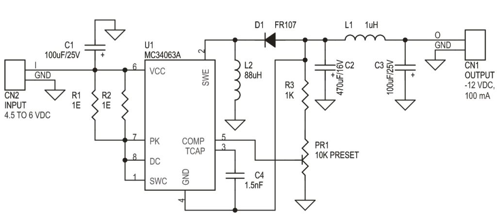
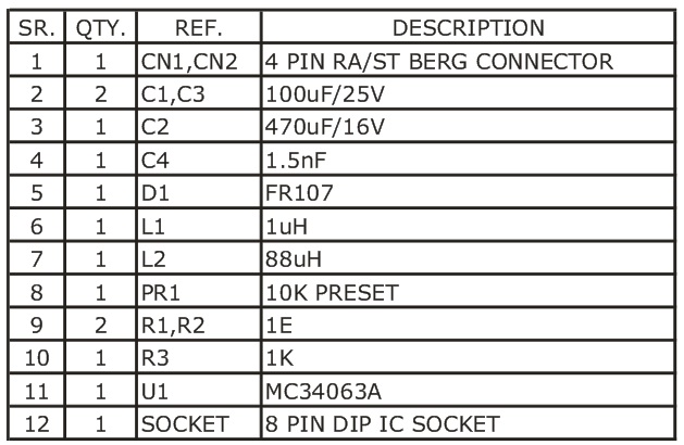
The DC/DC inverting switching regulators project is specifically designed to invert input voltages to negative outputs. It offer input voltage ranges from 4.5V to 6V and output -12V 100mA The MC34063A IC is heart of the project from On semiconductor. The MC33063A is a monolithic control circuit containing the primary functions required for DC-DC converters, This device consist of an internal temperature compensated reference, comparator, controlled duty cycle oscillator with an active current limit circuit, driver and high current output switch. This IC specially designed to be incorporated step-down, step-up, and voltage-inverting applications with minimum number of external components.
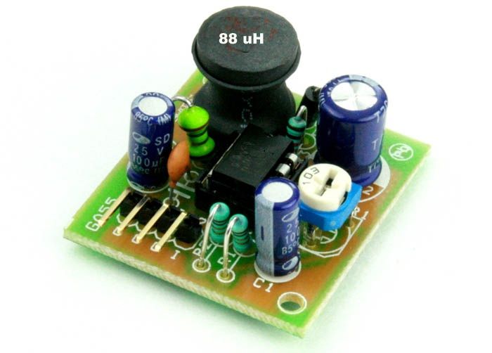
LT8610AX is a 3.5A, 42V input-capable synchronous step-down switching regulator, which operates in ambient temperatures up to 175°C. Synchronous rectification delivers efficiency as high as 95% while Burst Mode operation keeps quiescent current under 3.5 µA in no-load standby conditions.
The device’s 3.7V to 42V input voltage range is suitable for high temperature applications such as down-hole drilling equipment with power sources ranging from 5V to 40V. The LT8610AX’s electrical parameters are 100% tested at 175°C, offering a VREF accuracy of 2% over the entire -40°C to 175°C temperature range.
42V, 3.5A-out buck regulator operates at 175°C ambient – [Link]
This Design Idea circuit regulates the current through one or more LEDs, making it almost independent of supply voltage. Its main advantage is a very small dropout voltage, which can be less than 100mV. The design could find use on LED strips, where the voltage can vary along the length due to resistive drop, and small voltage changes result in large current changes
The DC/DC inverting switching regulators project is specifically designed to invert input voltages to negative outputs. It offer input voltage ranges from 4.5V to 6V and output -12V 100mA The MC34063A IC is heart of the project from On semiconductor. The MC33063A is a monolithic control circuit containing the primary functions required for DC-DC converters, This device consist of an internal temperature compensated reference, comparator, controlled duty cycle oscillator with an active current limit circuit, driver and high current output switch. This IC specially designed to be incorporated step-down, step-up, and voltage-inverting applications with minimum number of external components.
educ8s.tv has a new video on how to use a fingertip sensor with Arduino.
If you want to add biometric security features to your Arduino projects, an easy way to do so, is to add a fingerprint sensor module to it. In this video we demonstrate how easy to use a fingerprint sensor with an Arduino Nano and a small display.
I always wanted to try a fingerprint sensor module in order to learn more about its technology and use it in some of my projects in order to add biometric security to them. While searching for a nice and low cost sensor, I discovered this sensor module on Gearbest.com. The sensor costs around 30$ and you can find a link for it in the description of the video. Gearbest.com was kind enough to send a sample unit in order to test it and share my opinion about it with you.
Use a Fingerprint sensor module to add biometric security to your Arduino projects – [Link]
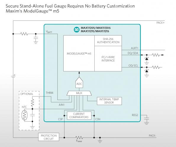
Implementing pack-side battery gauges in portable devices is easier and more secure, Maxim asserts, with its ModelGauge m5 portfolio of MAX17201/MAX17205 and MAX17211/MAX17215.
Fuel gauging can be difficult because battery voltage varies with temperature and load, while coulomb-counting requires sophisticated compensation to eliminate offset accumulation errors. Maxim’s ModelGauge m5 fuel gauges include a sophisticated algorithm that converts raw measurements such as battery voltage, current, and temperature into accurate state-of-charge (SOC%), absolute capacity (mAhr), time-to-empty, and time-to-full (while charging), all of which improve the user experience of the host device while enabling maximum run-time.