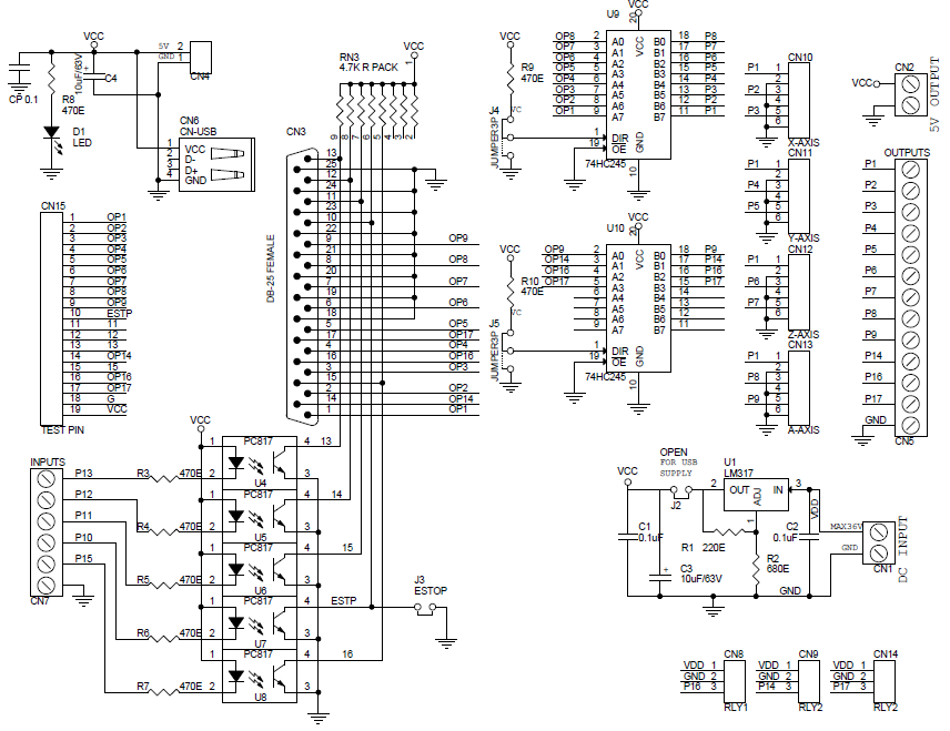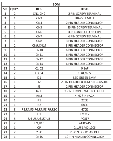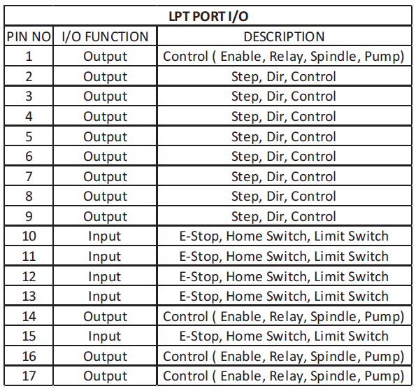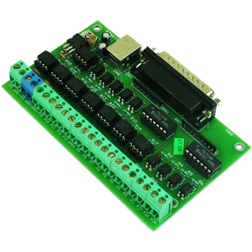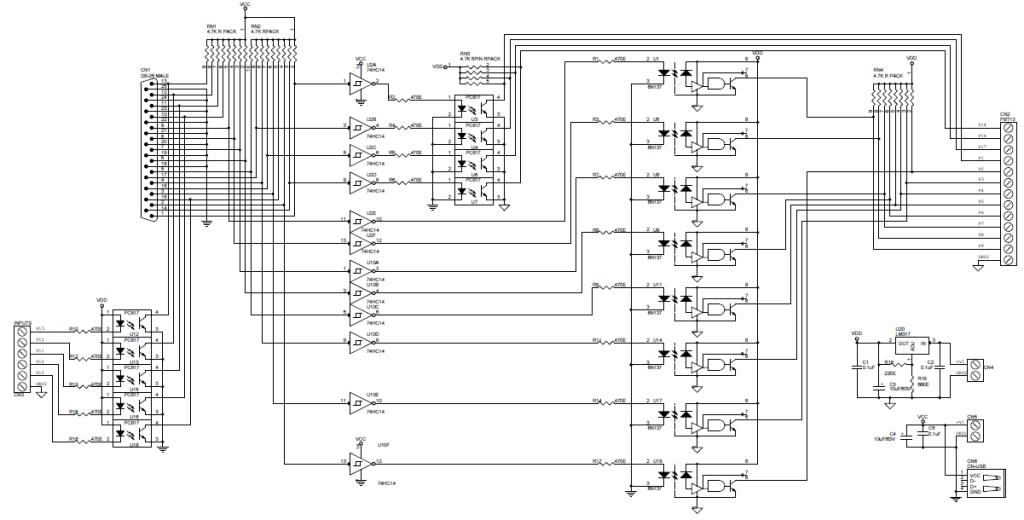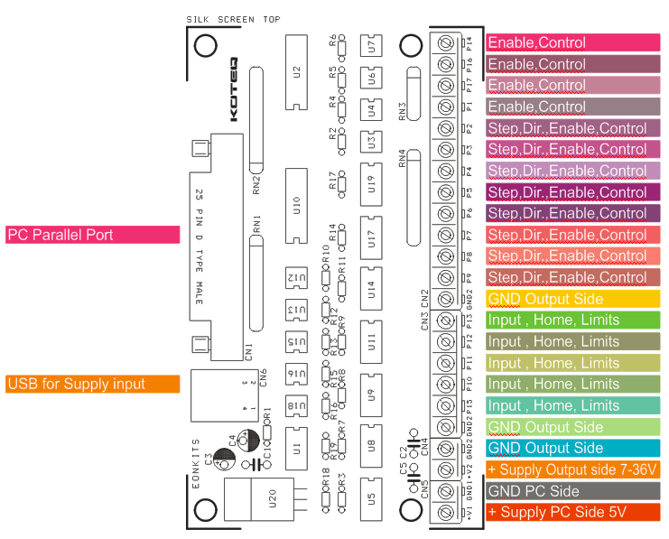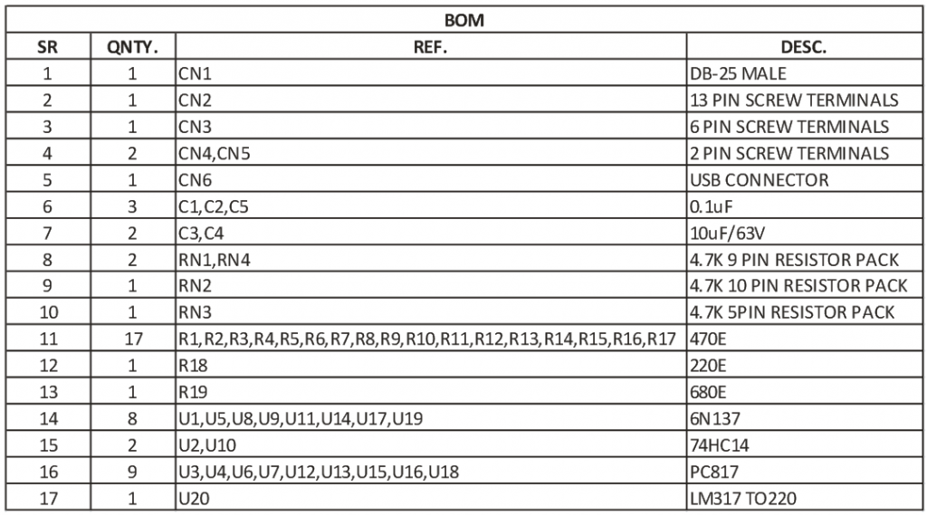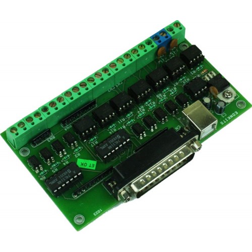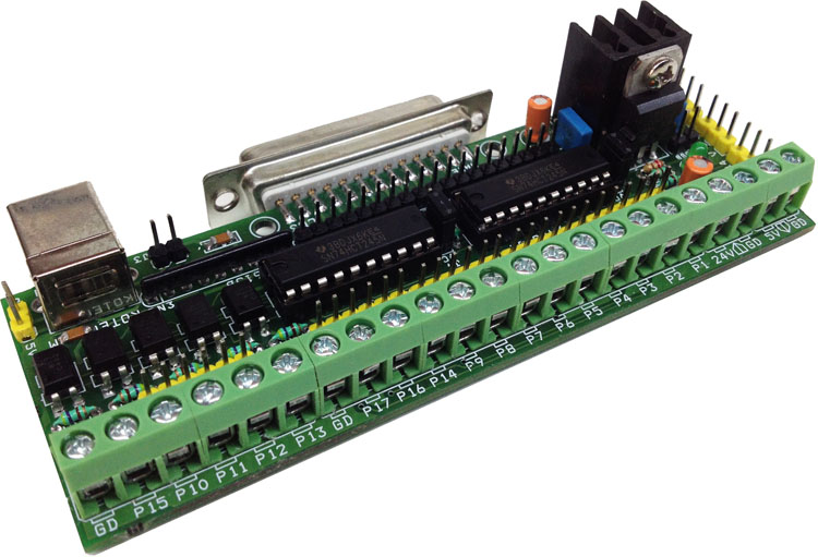
Parallel port I/O break out board designed for Hobby CNC, Routers and Motion controller , This Board is an easy solution to driver stepper Motor driver, AC Servo (with Step-DIR Driver) and DC servo (with Step-DIR Driver), The Board is compatible with various CNC software specially made for LPT port data out. The board has been tested with MACH3 CNC software. All outputs are buffered, all inputs are optical isolated and can be used as emergency switch, limit switch and home switch.
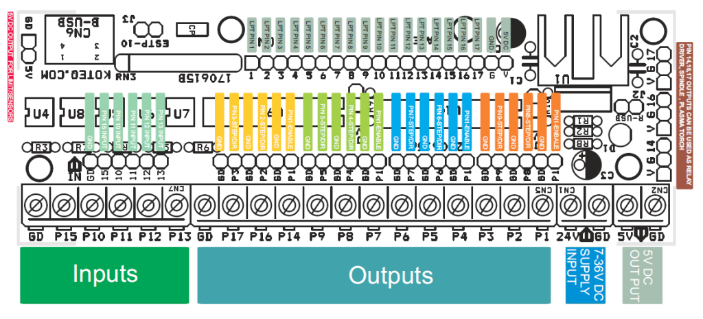
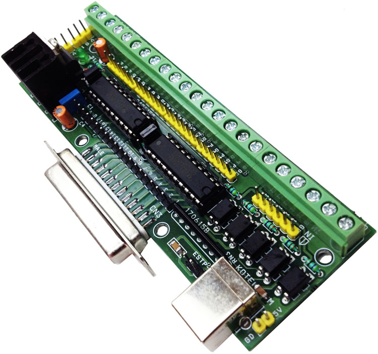
The board has 12 output pins that can control various devices such as stepping motor drivers, AC Servo Driver, DC Servo Driver, Plasma Torch, Pump for coolant, spindle, 5 Input pins are provided for limit or home switches, feedbacks, Emergency switch. All inputs has 470E for current controlled and TTL Voltage input required driving the inputs. This board can be powered with USB input or DC input supply 7V to 36V, keep jumper J2 open in case of USB supply input. Board has Screw Terminals for Inputs and out connections and also provided with 4X6Pin header connecters for outputs. J15 is connected directly to parallel port pins for testing purpose.
Note: For 24V input signal replace of R3, R4, R5, R6, and R7 with 2K2 Ohms.
Features
- Supply 7V to 36V DC
- 25 D SUB Female Connecter for PC LPT Port Interface
- On Board Power LED
- On Board USB Connector for Supply from PC or other USB source
- Jumper Selection for USB Supply Input or External Supply
- All Outputs are buffered
- All inputs are optically isolated
- Two Options for Outputs, Screw Terminals and Header Connectors
- 4X6Pin Header for easy motor driver interface
- On Board L317 Regulator for 5V DC
- Heat sink for regulator
- 5V DC Output for External Circuits
- 3X3 Header Connector for Relay Driver for Spindle, Plasma, Laser, Pump ON/OFF
Parallel Port Breakout board with Buffer for CNC & Routers – [Link]