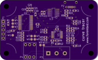
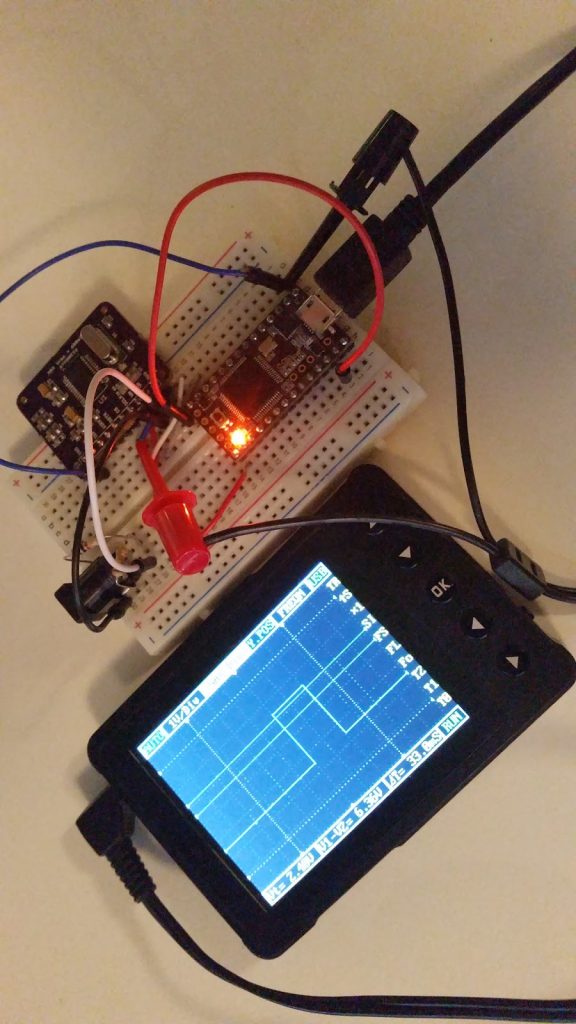
Jason Jones has tipped us with his latest project. He is working on a semiconductor curve tracer and details his progress on his website.
I have thought about this a lot recently and – in order to get the cost down – the unit must have a cheap or available power supply and must coopt the screen for another device. The first and easiest thing that comes to mind is to simply use USB for the power supply and use your PC screen as the screen. This is the direction that we will go for the moment in order to keep things simple. Up to this point, we have a screen and power supply without even starting the design.
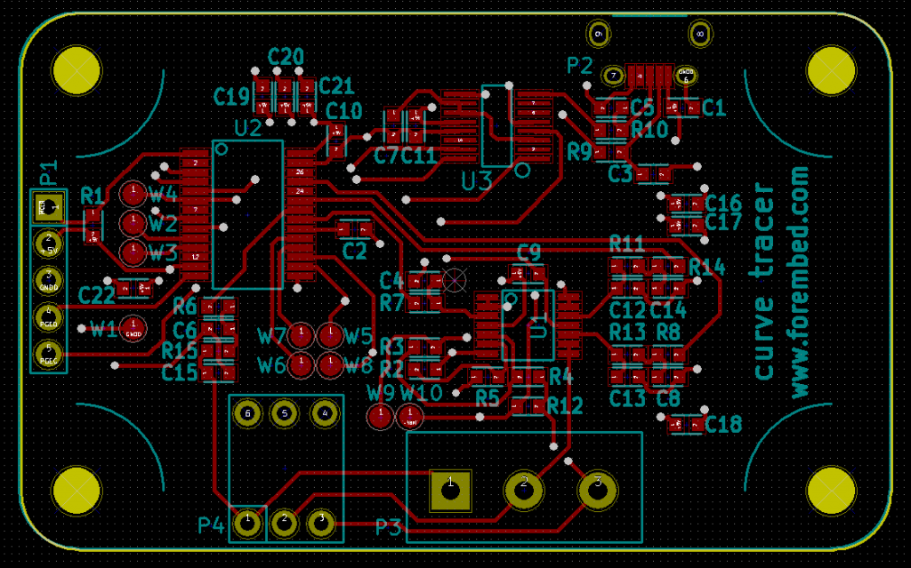
This is a tutorial on how to use a 433MHz long range transmitter/receiver with Arduino.
I just explain how i have use the 433MHz RF Long Distance Transmitter / Receiver Pair and a arduino to install it on my rc truck for a firework ignition, lamp , pan tilt camera system
How to Use Arduino and a RF 433 Long Range – [Link]
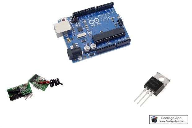
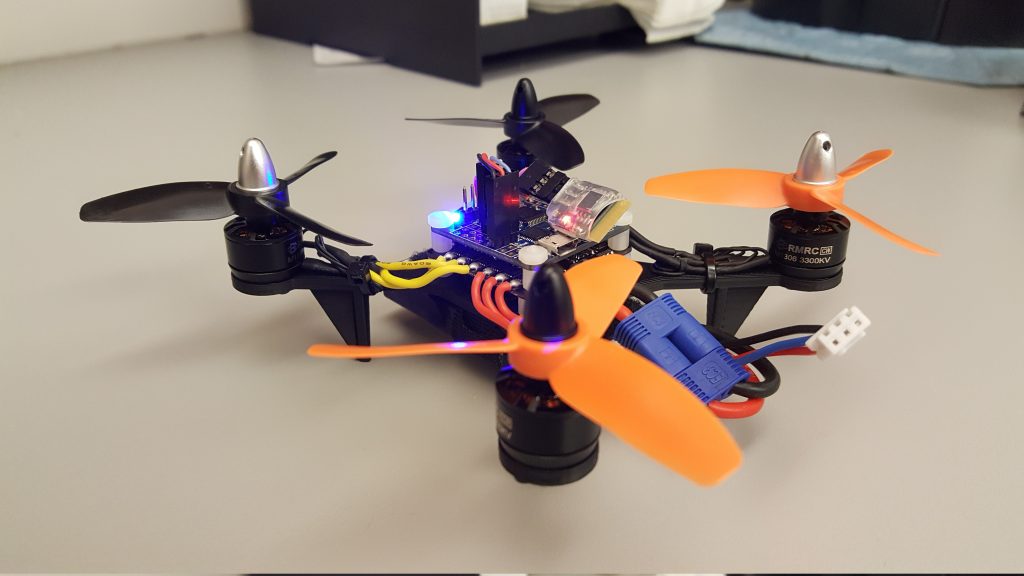
Simon D. Levy designed and build a mini quadcopter with 3D printed frame and custom C++ firmware. See the full project notes including bill of materials and more photos on the link below, and check out Simon’s blog on the C++ firmware here.
I wanted to try my hand at a true “DIY” project, designing and building my own micro quadcotper frame and writing my own firmware in C++. In this post I will describe the frame and build; in my next post I will talk about the firmware.
DIY Mini Quadcopter with 3D-Printed Frame and Custom Firmware – [Link]
Tisham Dhar designed an ATM90E26 energy meter breakout board which can be used in single phase power measurements.
After designing and testing the ADE7763 based Energy Monitor Breakout Board, I started looking around for cheaper and more modern alternatives.I came across the Atmel ATM90E26 Smart Metering IC with dual communication options – UART/SPI and multiple metering modes (tamper proofing with current sensing on live and neutral).
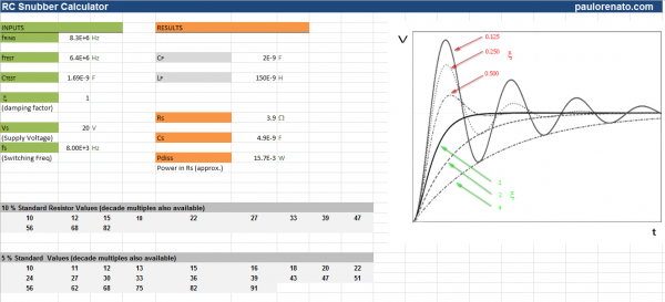
Paulo has developed an Excel-based calculator that eases the design of RC snubbers in power switching applications:
In power switching applications, a designer often has to contend with spurious oscillations. These are the result of parasitic capacitances and inductance on the board and behave like the step response of an RLC circuit. These transients can induced undesired noise in neighboring circuits and create over voltage spikes that can compromise long term component reliability.
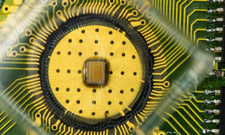
For the first time, scientists at IBM Research have demonstrated reliably storing 3 bits of data per cell using a relatively new memory technology known as phase-change memory (PCM).
The current memory landscape spans from venerable DRAM to hard disk drives to ubiquitous flash. But in the last several years PCM has attracted the industry’s attention as a potential universal memory technology based on its combination of read/write speed, endurance, non-volatility and density. For example, PCM doesn’t lose data when powered off, unlike DRAM, and the technology can endure at least 10 million write cycles, compared to an average flash USB stick, which tops out at 3,000 write cycles.
IBM scientists achieve storage memory breakthrough – [Link]
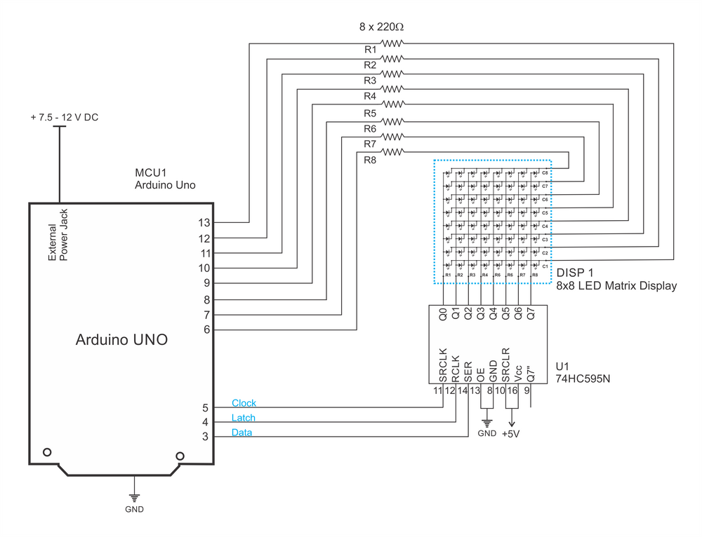
This tutorial will show how to interface a 8×8 LED matrix with Arduino. Example code is provided.
LED matrix displays can be used to display almost anything. Most modern LED sign boards uses various types of matrix boards with controllers. In this tutorial we are going to interface a single color 8×8 LED matrix with Arduino and display few characters in it.
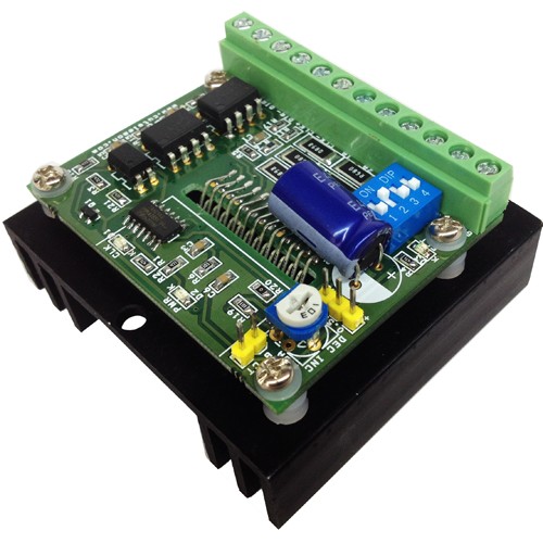
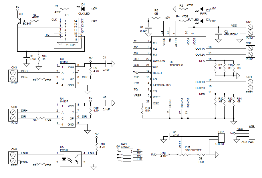
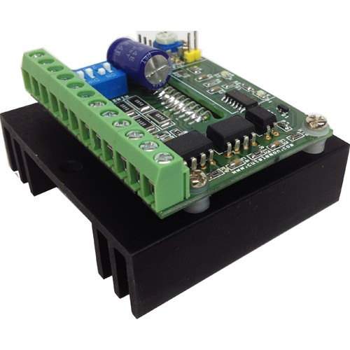
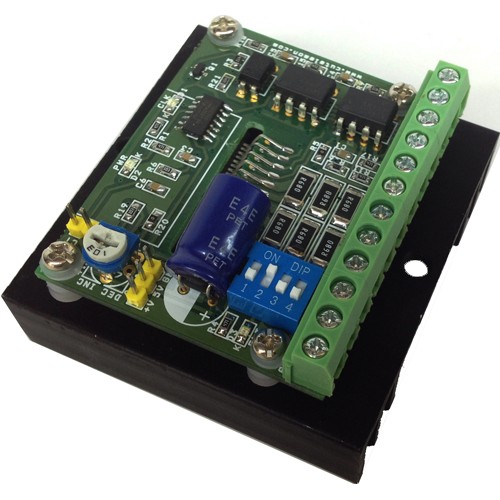
Bipolar stepper drive board described here has been designed around TB6600HG IC. The TB6600HG is PWM chopper type single chip bipolar sinusoidal micro-step stepping driver. Maximum Load 4.5A, Supply 10V to 42V DC.
Features
Based on Single chip and Second chip for auto half current control
Suitable for Nema17, Nema23, Nema34 bipolar stepper motors
Suitable for 4Wires, 6 wires and 8 wires stepper motor.
Forward and reverse rotations available
Selectable Phase (Micro-step) drives 1/1, 1/2, 1/4, 1/8, and 1/16
Maximum Input supply 42V DC Minimum Input supply 10V DC
Output current 4.5Amps
Output Fault Monitor LED indicator
On Board Power LED indicator
On Board step pulse input indicator
Standby auto half current reduction circuitry onboard
Built in Thermal shutdown (IC)
Built in under voltage lock out (UVLO) circuit (IC)
Built in over current detection (ISD) circuit (IC)
Large capacitor to handle inrush current
4.5Amps Bipolar Stepper Motor driver based on TB6600 – [Link]
Bipolar stepper drive board described here has been designed around TB6600HG IC. The TB6600HG is PWM chopper type single chip bipolar sinusoidal micro-step stepping driver. Maximum Load 4.5A, Supply 10V to 42V DC.
Features
Based on Single chip and Second chip for auto half current control
Suitable for Nema17, Nema23, Nema34 bipolar stepper motors
Suitable for 4Wires, 6 wires and 8 wires stepper motor.
Forward and reverse rotations available
Selectable Phase (Micro-step) drives 1/1, 1/2, 1/4, 1/8, and 1/16
Maximum Input supply 42V DC Minimum Input supply 10V DC
Output current 4.5Amps
Output Fault Monitor LED indicator
On Board Power LED indicator
On Board step pulse input indicator
Standby auto half current reduction circuitry onboard
Built in Thermal shutdown (IC)
Built in under voltage lock out (UVLO) circuit (IC)
Built in over current detection (ISD) circuit (IC)
Large capacitor to handle inrush current
Applications
Robotics
Large format Size Printers
CNC
Routers
3D Printers
Machine Automations
Camera Pan Tilt Heads
Slot Machine
Vending Machine
Heat-sink and Thermal Shutdown
The board has current sense resistors and these resistors has been set as per maximum load current 4.5A, If you use lower current motor, please set the PR1-Preset ( Potentiometer) to the required level for the motor. At maximum current load TB6600 IC will overheat in some time and a RED LED turns on. This LED goes off once the temperature falls to a safe operating level.
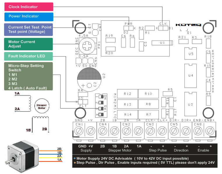
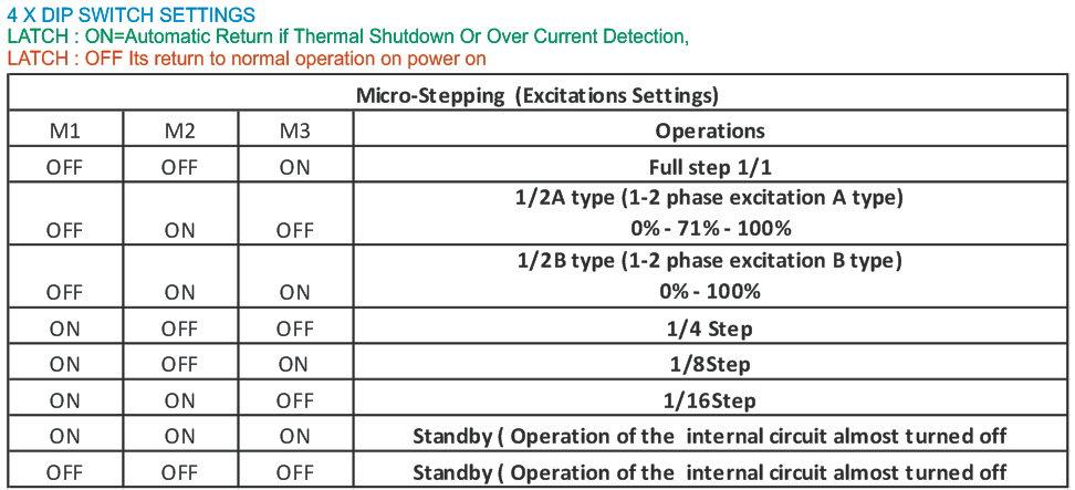
Micro Stepping
A 4way DIP switch is used to set the micro step modes (Full, Half, Eight, Sixteenth), please see the table for Micro step settings. DIP Switch settings should be changed when power is off so the correct selection is active at power up.
Step Pulse
Minimum positive duty cycle of the input step pulse should be 2.2us and required 5V (TTL) signal. A positive going pulse on the step input activates a step operation.
Current Settings
Average drive current can be set using a Preset (On Board PR1 Potentiometer). CN7 (CT) onboard connector is provided to measure the voltage to set the motor current (torque). Voltage range to set the torque 0.3V to 3.5V
Cautions
Never connect or remove supply wires, motor wires, or input interface when power is on, this can cause damage to drive.
Switch the Power to set the Micro stepping
Before using this drive, please have proper information about stepper motors, Motor impedance, Inductance and other specs.
Inputs
All Inputs are optically isolated to prevent the device for any kind of noise, short circuits.
Enable: Required 5V DC input, Set high Input disabled the drive, Set low input Enable the drive
Dir.: Required 5V DC input, Set high Input CW Rotation, Set low input CCW Rotation, Direction of the motor depends how stepper motor has been wired.
CLK: Step Pulse required 5V DC TTL pulse
Outputs
4 Wires, 6 Wires, 8 Wires Motors can be used with this drive in bipolar mode.
On board LED for Alert
4XDIP SWITCH
SW4 (LATCH): ON=Automatic Return if Thermal Shutdown Or Over Current Detection OCCURS
SW4 (LATCH) : OFF= On Fault condition required power on/off
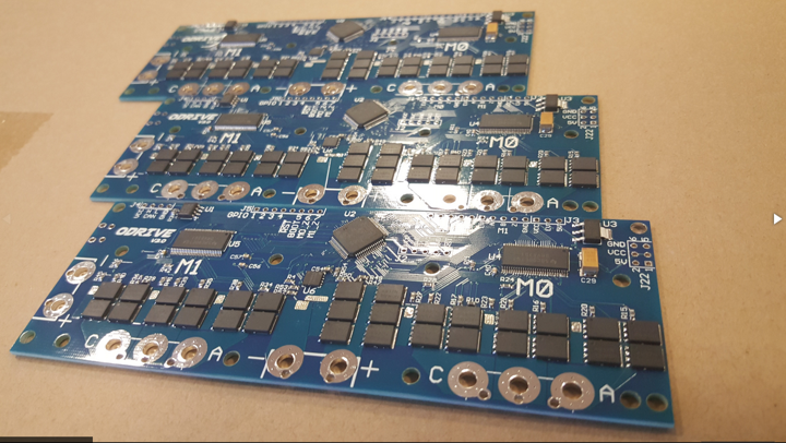
Oskar Weigl @ hackaday.io designed a brushless motor controller able to drive 2 motors.
Hobby brushless motors are incredibly cheap and powerful. However we need a way to make robots out of them. ODrive is that way.
Stepper motors are ubiquitous in hobby robotics projects: If you make a robotics or automation project today, it is very likely you will use them. Almost all DIY projects from 3D printers and CNC mills, to other kinds of projects like air hockey robots, use them. However in industrial automation, brushless servomotors have taken over, and it’s clear why: They don’t lose steps, are much more powerful, efficient, and silent.