

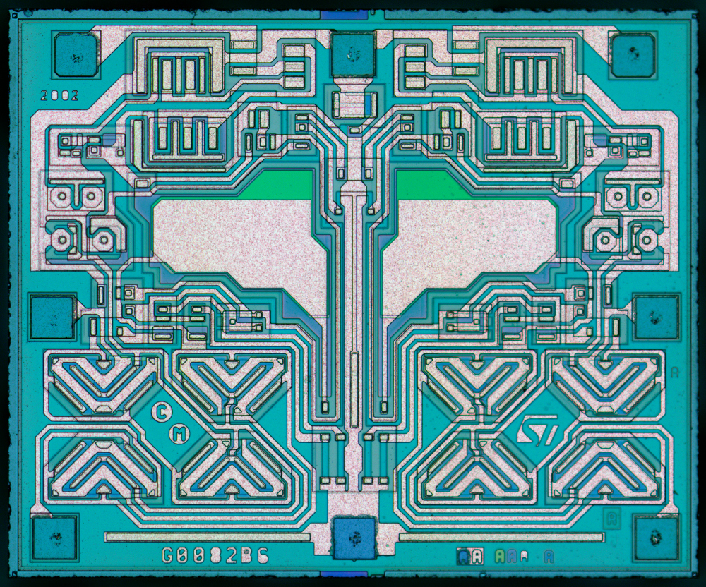
A new die shoot from zeptobars.com. Die size 1547×1279 µm.
ST TL072 – dual JFET opamp die-shot – [Link]
A new die shoot from zeptobars.com. Die size 1547×1279 µm.
ST TL072 – dual JFET opamp die-shot – [Link]
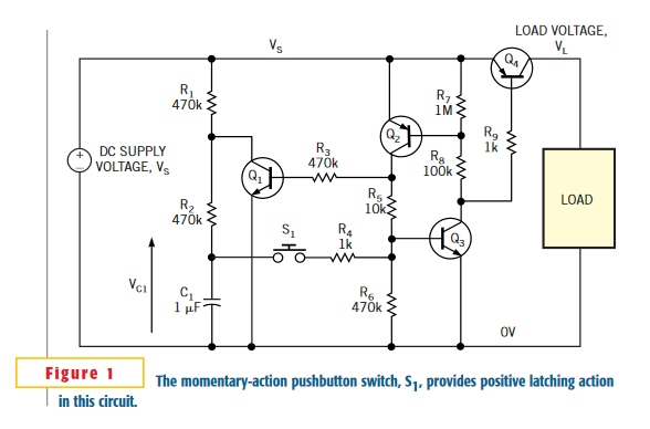
Anthony Smith @ edn.com published a push button latching circuit able to control a load with a single push of a button.
The circuit in Figure 1 shows how you can use a simple, momentary-action, SPNO (single-pole, normally open) pushbutton switch to latch power to a load. Requiring just a handful of common, garden-variety components, the circuit works over a wide voltage range and is ideal for single-cell applications, because it can operate at voltages as low as 1V or less. Transistors Q2 and Q3 form an SCR-like structure that functions as a simple latch, Q4 switches power to the load, and S1 is the momentary pushbutton switch.
Latching power switch uses momentary-action pushbutton – [Link]
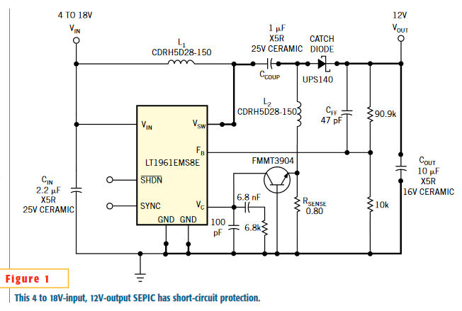
Keith Szolusha@ edn.com writes:
In certain dc/dc-converter applications, on-chip, cycle-by-cycle current limit may be insufficient protection to prevent a failure during a short circuit. A nonsynchronous boost converter provides a direct path from the input to the short circuit through the inductor and the catch diode. Regardless of current-limit protection in the IC, when a short circuit exists in the load, extremely high currents that flow through the load path can damage the catch diode, the inductor, and the IC. In a SEPIC (single-ended, primary-inductance-converter) circuit, the coupling capacitor breaks this path.
Single transistor provides short-circuit protection – [Link]
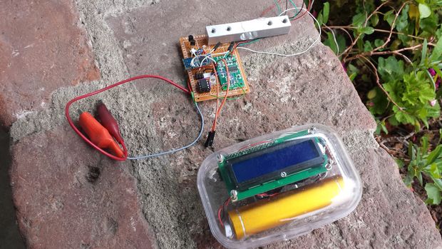
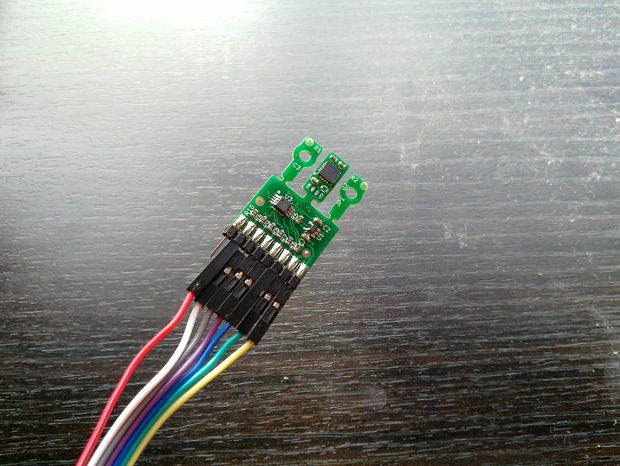
This is a wireless digital scale using ATTiny85 microcontroller and HM-10 Bluetooth low energy transmitter/receiver:
This scale is wireless. It may be useful where you can’t operate a normal scale, due to the weather outside, or if you don’t want to scare birds or other creatures away. With this scale you can weigh them. In this instructable, I used a 0 to 1 Kg load cell since I wanted to weigh hummingbirds and orioles that visited our nectar feeder.
Wireless digital scale – [Link]
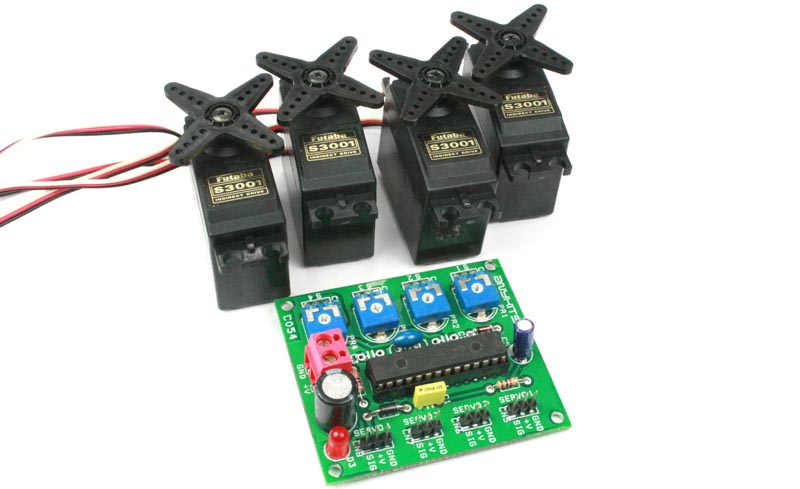
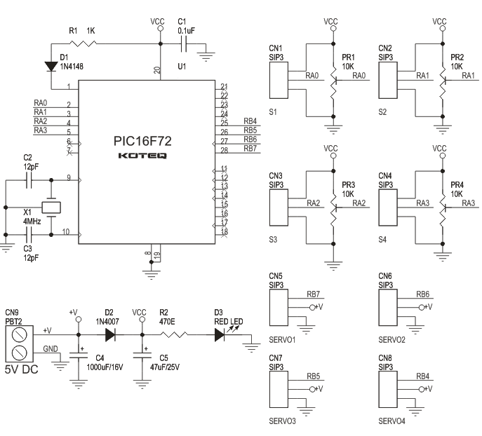
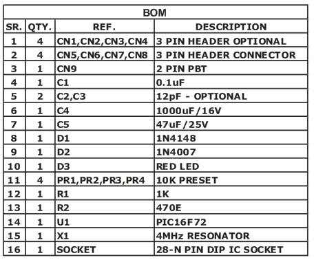
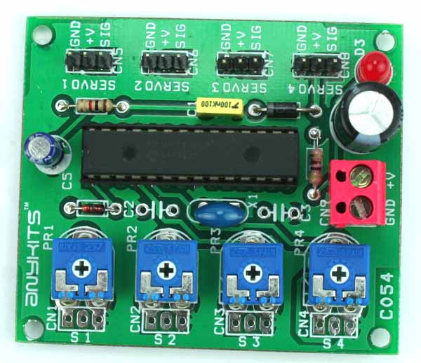
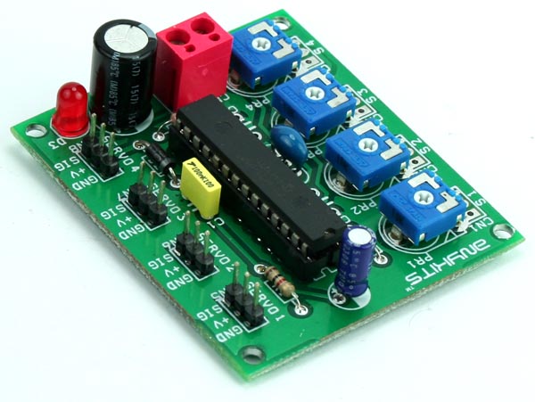
This PIC microcontroller based RC driver is able to control 4 RC Servo by on board independent 4 potentiometer , 4X3PIN header for RC servo interface, screw terminal for supply input, on board power LED, optional 4X3PIN header connector for external potentiometer.
This PIC microcontroller based RC driver is able to control 4 RC Servo by on board independent 4 potentiometer , 4X3PIN header for RC servo interface, screw terminal for supply input, on board power LED, optional 4X3PIN header connector for external potentiometer.
Note: CN1, CN2, CN3, CN4 optional connector to connect external potentiometer (Omit on board preset for external potentiometer)
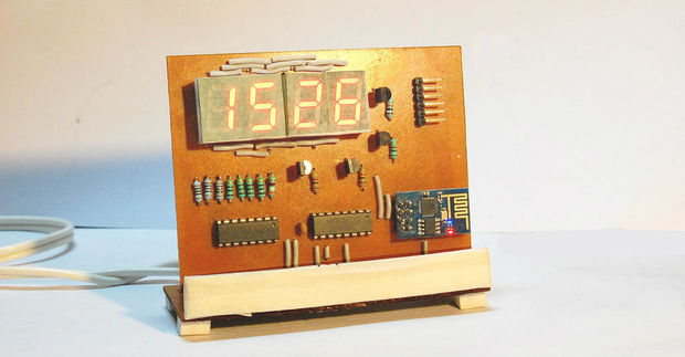
This project is a wifi synchronised desktop clock using 7-segment displays. The heart of the project is a ESP8266 board.
The ESP8266 is a awesome chip; with integrated WiFi, 80MHz clock speed, total 160kb RAM, 512kb of flash memory, and a ton of other features, it makes a regular Arduino look like a joke. The project shown in this Instructable is based solely on the ESP8266-01 module, unlike several other projects on the web where it is used in tandem with another microcontroller. This makes it great demonstration of the capabilities of the ESP chip.
ESP8266 Desktop Clock – WiFi Synchronised – [Link]
This project shows how to measure temperature data from a TSYS01 Temperature Sensor board using Arduino:
While studying in university we were challenged as part of a course work into designing a box with very accurate temperature control. If the project were to succeed, multiple boxes were to be built and used in a research project studying the effect of surface material on the perceived temperature of flooring and other building materials.
How to measure temperature very accurately with an Arduino – [Link]
Michael Dunn@ edn.com discuss about current sense on the high side of power source.
At their heart, the majority of DC current sense circuits start with a resistance in a supply line (though magnetic field sensing is a good alternative, especially in higher-current scenarios). One simply measures the voltage drop across the resistor and scales it as desired to read current (E = I × R (if I didn’t include this, someone would complain)). If the sense resistor is in the ground leg, then the solution is a simple op-amp circuit. Everything stays referenced to ground, and you only have to be careful about small voltage drops in the ground layout.
Sensing current on the high side – [Link]
This is the second and final article of the Eagle Tips from allaboutcircuits.com:
Before searching on the internet for new libraries to add to Eagle, first make sure that your device does not already exist in your local libraries. To check, use a search pattern that includes ‘*’.
For example, if you want to add a 7805 5v regulator, you must search for *7805* instead of 7805. This will search for any part with 7805 in the middle of the name, without regard for the beginning or end of the part name.
Eagle CAD Tips and Tricks Part 2 – [Link]


