
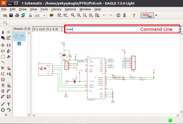
Most hobbyists and many professionals use Eagle CAD as a daily tool in designing schematics and laying out PCB. Yahya Tawil is going to share with us the most important tips and tricks for using Eagle CAD, which make your work much easier and faster.
My advice is to keep one hand on the mouse to do wiring, etc. inside the editor workspace and use the other hand on the keyboard to write commands and select tools. My advice of using the keyboard is not only for selecting tools. You will see the other benefits of using the keyboard in Eagle CAD in the rest of this series.
Eagle CAD Tips and Tricks – [Link]


Mover Kit encourages movement! It’s a game, speed-activated bike light, disco bracelet – whatever a kid can make, move & code it to be.
The Mover Kit is an intuitive way for kids ages 8 and over to learn the fundamentals of electronics, programming and solve problems creatively. It encourages kids to learn by doing what they do best – being active and playing! The Mover Kit was named Forbes’ Toy to Watch in 2016 and is loved by 300 kids that have tested it out so far.
Mover Kit – The first active wearable that kids make & code – [Link]

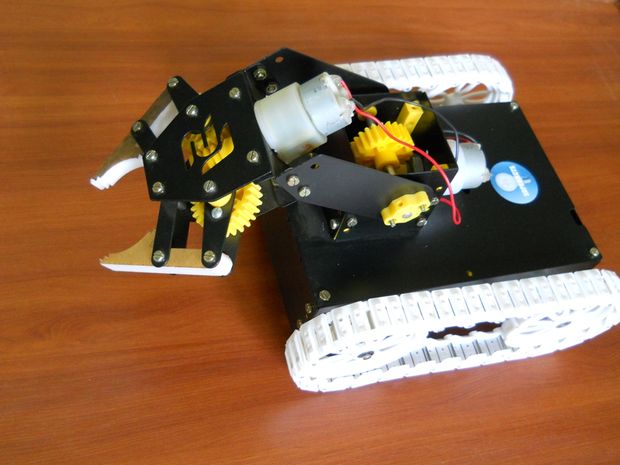
Sameer tipped us with his latest build of an arduino robot which is controlled by an Android smartphone using Bluetooth.
Pick N Place robot is a basic level robot for beginners and leaders to learn all about the laws & concepts of Physics, Electronics & Mechanics hence it helps one to inherit this knowledge as one is implementing it. It helps you to get a feel of what robotics is all about.
Features:
Arduino programming, Bluetooth Application based Android smartphone control, Wheel with track belt drive, Pick and place operation by gripper, Easy circuit implementation
Arduino “Pick N Place” Android Robot – [Link]

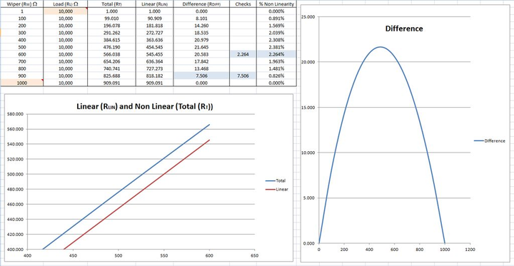
Tecwyn Twmffat @ instructables.com discuss about the notlinearity introduced by adding a pull down resistor and why you may get unpredictable readings from your ADC.
For many years I found that I would get strange, unpredictable, readings from my sensor related projects at the maximum and minimum locations when using analogue digital convertors (ADCs). I always blamed this on poorly designed micro processors and never for once thought that it might be my own circuit designs at fault ….. until now.
Analogue Sensors – Calculate the Nonlinearity Introduced by a Load or Pull Down Resistor – [Link]

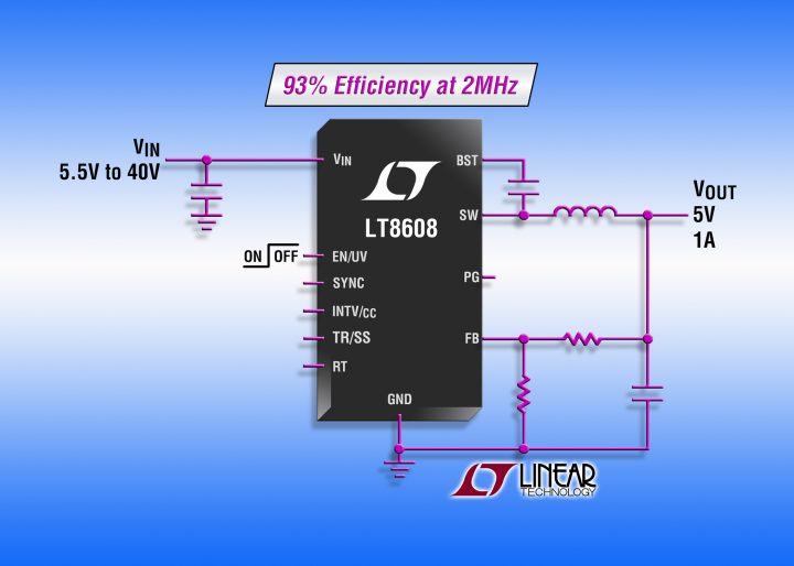
Linear Technology Corporation announces the LT8608, a 1.5A, 42V input synchronous step-down switching regulator. A unique synchronous rectification topology delivers 93% efficiency while switching at 2MHz enabling designers to avoid critical noise-sensitive frequency bands, such as AM radio, while using a very compact solution footprint. Burst Mode® operation keeps quiescent current under 2.5μA in no-load standby conditions making it ideal for always-on systems. Its 3.0V to 42V input voltage range makes it ideal for automotive applications which must regulate through cold-crank and stop-start scenarios with minimum input voltages as low as 3.0V and load dump transients in excess of 40V. Its internal 2A switches can deliver up to 1.5A of continuous output current. The LT8608 maintains a minimum dropout voltage of only 200mV (@500mA) under all conditions, enabling it to excel in scenarios such as automotive cold-crank. Spread spectrum frequency modulation and special design techniques offer low EMI operation to minimize noise concerns in automotive and industrial environments. Furthermore, a fast minimum on-time of only 45ns enables 2MHz constant frequency switching from a 16V input to a 1.5V output. The LT8608’s 10-lead thermally enhanced MSOP package and high switching frequency keeps external inductors and capacitors small, providing a compact, thermally efficient footprint.
Buck regulator accepts 3.0-V to 42-V input – [Link]
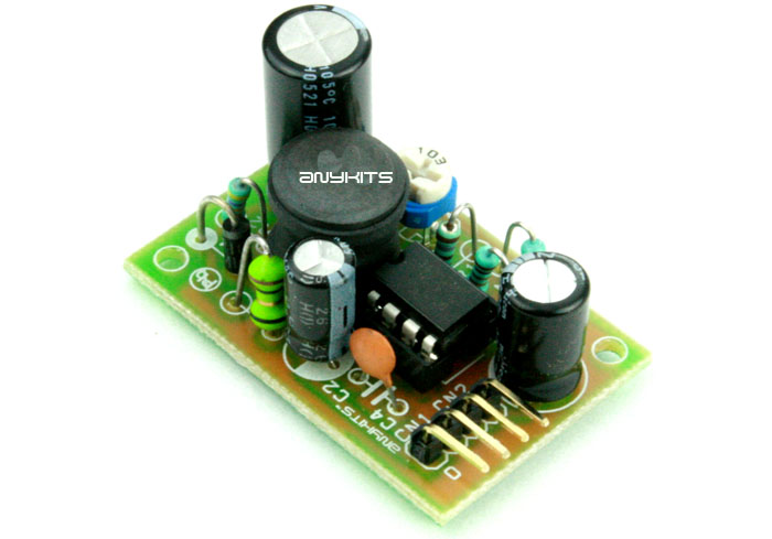
The Step-Up DC-DC Converter project provides 28V, 175mA output with input of 12V DC. The MC34063A IC is heart of the project from On semiconductor. The MC33063A is a monolithic control circuit containing the primary functions required for DC-DC converters, This device consist of an internal temperature compensated reference, comparator, controlled duty cycle oscillator with an active current limit circuit, driver and high current output switch. This IC specially designed to be incorporated step-down, step-up, and voltage-inverting applications with minimum number of external components.
Features
- Input 12V DC
- Output 28V, 175mA
- Output Fine Adjustable By On-board Preset
- Header Connector for Output/Input Connections
- Low Standby Current
- On Board Filter To Provide Low Ripple Output
- PCB Dimensions 28mmX33MM
12V to 28V Step Up DC-DC Converter – [Link]

The Step-Up DC-DC Converter project provides 28V, 175mA output with input of 12V DC. The MC34063A IC is heart of the project from On semiconductor. The MC33063A is a monolithic control circuit containing the primary functions required for DC-DC converters, This device consist of an internal temperature compensated reference, comparator, controlled duty cycle oscillator with an active current limit circuit, driver and high current output switch. This IC specially designed to be incorporated step-down, step-up, and voltage-inverting applications with minimum number of external components.
Features
- Input 12V DC
- Output 28V, 175mA
- Output Fine Adjustable By On-board Preset
- Header Connector for Output/Input Connections
- Low Standby Current
- On Board Filter To Provide Low Ripple Output
- PCB Dimensions 28mmX33MM
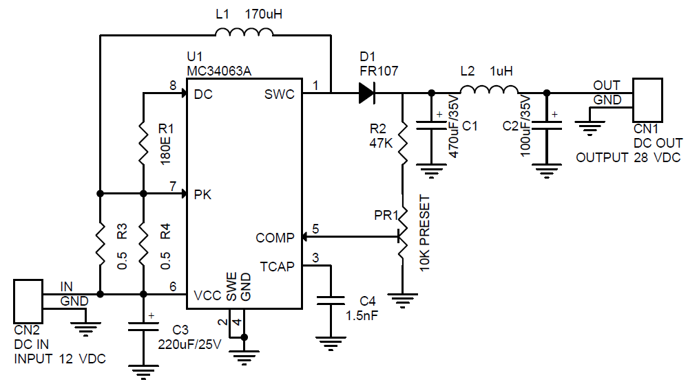
Schematic
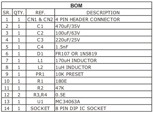
Parts List

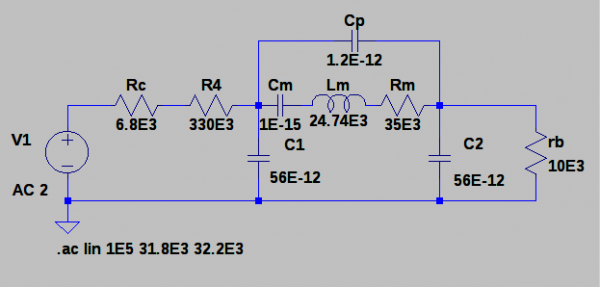
How to Actually Make it Oscillate?
Now for an oscillator to work, we need an amplifier with a gain of greater than 1, and a phase shift of 360 degrees to get positive feedback.
First problem – the transistor was saturated, with Vc stuck near 0V. For an oscillator to start noise gets amplified, filtered by the crystal, amplified again etc. I reasoned that if the amplifier wasn’t biased to be linear, the oscillations couldn’t build up. So I reduced the collector resistor to 6.8k, and changed the the base bias resistor to 1.8M to get the collector voltage into a linear region. So now we have Vc=3.2V with a 5V supply.
Troubleshooting a 32kHz Crystal Oscillator – [Link]
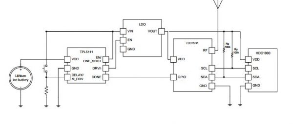
Ultra Low-Power (35nA!) Programmable Timer using TI TPL5111.
Imagine a system for example that has to work from a small coin cell for 5-10 years.
TPL5111 solves a typical problem in low power wireless systems- things need to be off most of the time, and wake up periodically to transmit.
Ultra Low-Power (35nA!) Programmable Timer using TI TPL5111 – [Link]

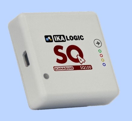
Harry Baggen @ elektormagazine.com reviews the ScanaQuad, a new series of tiny 4 channel logic analyzers. The ScanaQuad series consists of four modules (SQ25, SQ50, SQ100 and SQ200), which mainly differ in the sampling rate.
The French company Ikalogic has been making logic analyzers modules since 2010 with a USB port for connection to a laptop or desktop PC. Nothing special, you might say, but late last year they launched a new series of four-channel logic analyzer modules.
Review: ScanaQuad – a super-small logic analyzer – [Link]
