In this video educ8s.tv is going to show us how to wirelessly update the code of our Arduino project, using the WeMOS D1 ESP8266 based board. This is an impressive, and very useful feature.
A few weeks ago, we took a first look at the very promising new board, the WeMos D1. You can watch that video by clicking in the card here. The Wemos D1 is an ESP8266 based board which resembles the Arduino Uno board but it offers a lot more. Huge processing power, large memory and WiFi at a very low cost, less the 8$! You can find a link for the board in the description of the video.
WeMOS D1 ESP8266 Over the Air (OTA) update – [Link]
R. Colin Johnson @ eetimes.com discuss about quantum dots applications and how scientists use them to boost photovoltaic output.
LAKE WALES, Fla—Quantum dots are already being used commercially to boost the output and expand the color range of ultra-high-definition televisions, eliminating the need for the rare earth elements for which China as virtually cornered the market. Quantum dots, however, can also be used to absorb light to boost the output of photovoltaics, photocatalysts, light sensors, and other optoelectronic devices according to Brookhaven National Laboratory (Upton, N.Y.)
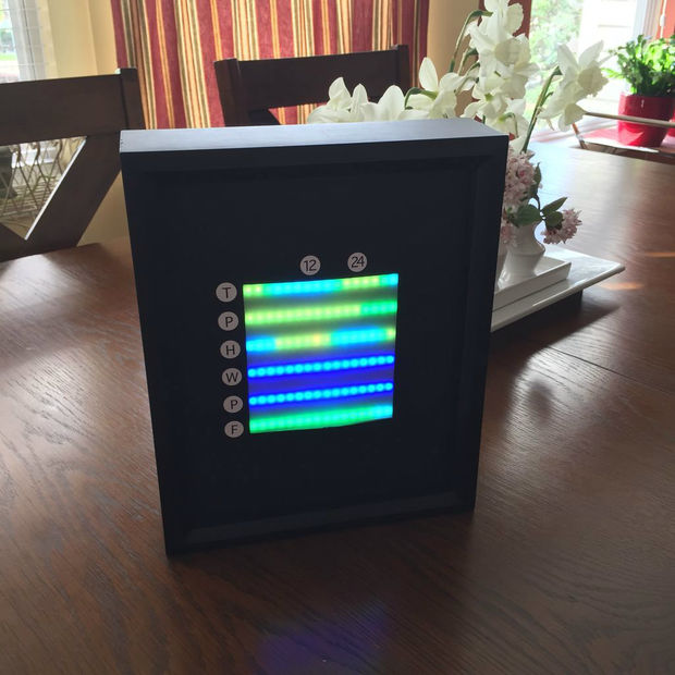
AughtNaughtZero @ instructables.com posted his latest project, a LED matrix visualizing data from a weather website such as temperature, pressure, humidity, wind speed etc.
This project utilizes a 6 x 16 matrix of RGB LEDs to visualize a weather forecast pulled from the Weather Underground API. A Raspberry Pi runs a python program designed to fetch weather forecast data from the API at regular intervals, parse the data into temperature, pressure, humidity, wind speed, chance of precipitation, and weather condition arrays, and then colorize and display that data across the LED matrix.
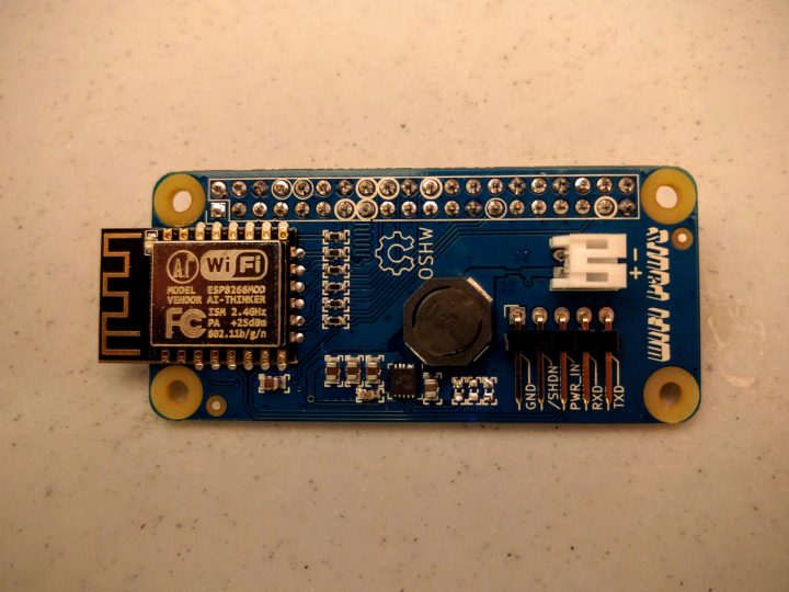
This board will let you add WiFi functionality to your Raspberry Pi Zero without having to sacrifice the only available high speed USB port. The board is based on ESP8266 Wifi module.
WiFi on a Raspberry Pi using the HAT connector and an ESP8266. The goal of this project is to add WiFi to the Raspberry Pi Zero while keeping the USB port free for devices or OTG connection to another host.
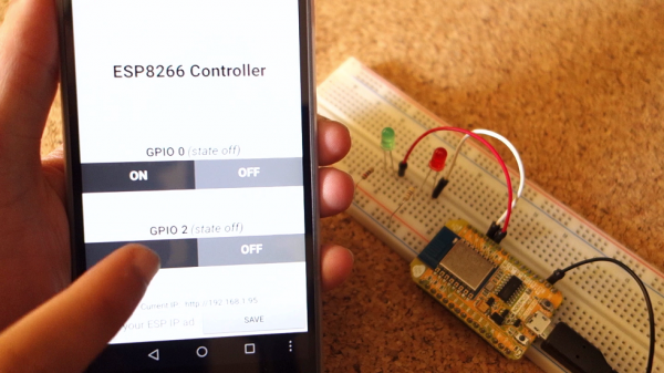
Rui Santos from Random Nerd Tutorials tipped us with his latest tutorial on how to build an Android app using the MIT App Inventor software that allows you to control the ESP8266 GPIOs:
ESP8266 controlled with Android app (MIT App Inventor) – [Link]
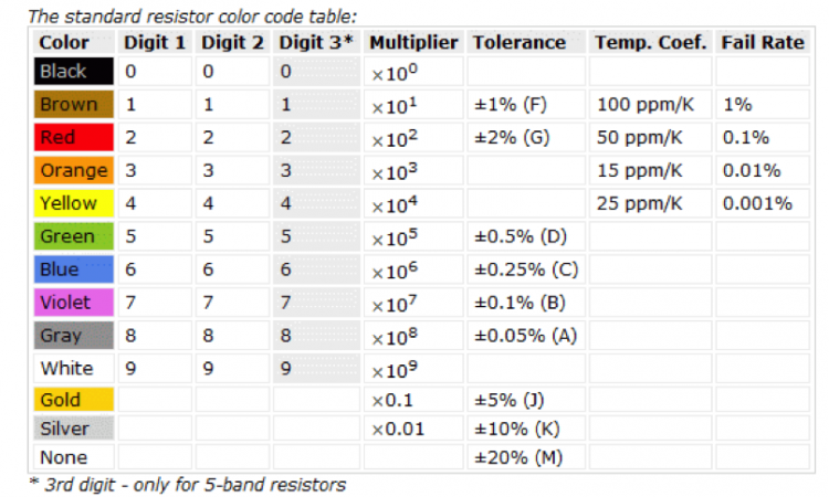
In this guide Sanket Gupta @ octopart.com explains how to select a resistor from a range of common resistor types.
In this blog, we will explain all the different types of resistors, their merits and demerits, and popular applications. We have included some recommendations for commonly used resistor series with high supply chain availability from the Common Parts Library and Seeed Studio’s Open Parts Library, and have linked to pre-created search on Octopart.
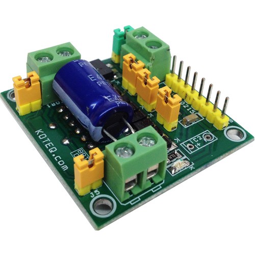
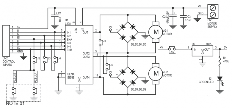
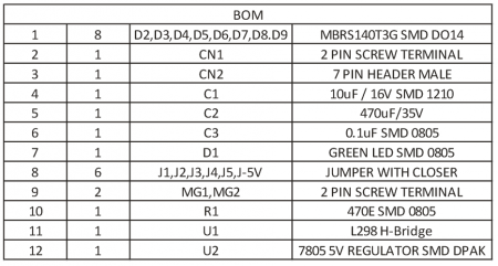
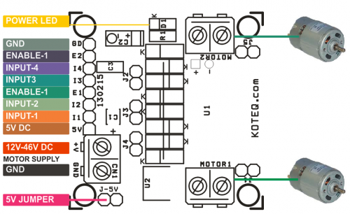
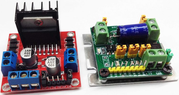
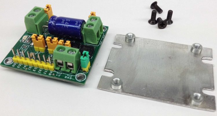
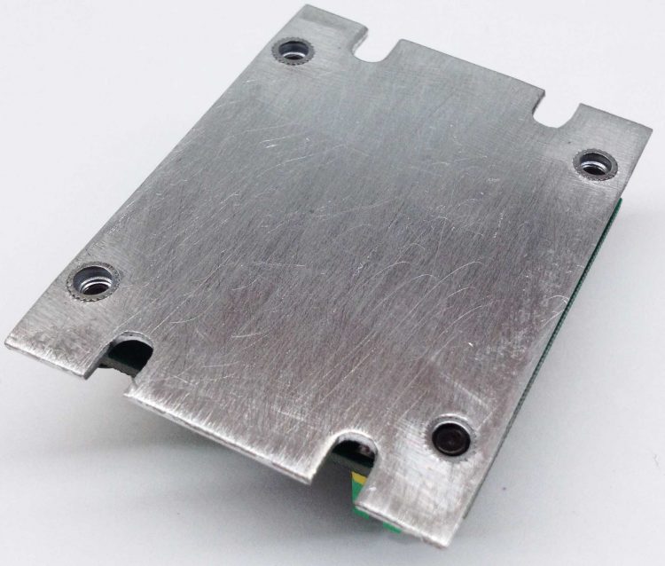
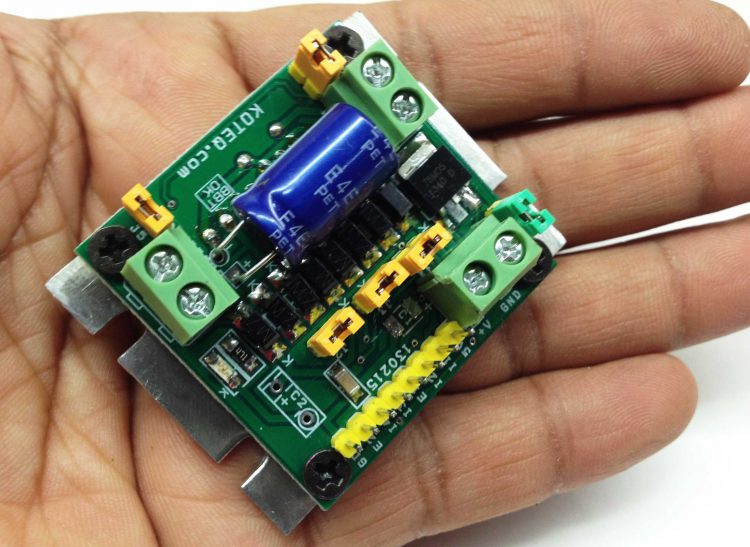
Dual Motor L298 H-Bridge Control project can control two DC motors connected to it. The circuit is designed around popular dual H-Bridge L298 from ST. This board can be configured to drive a single motor with high current rating also. This can be achieved with the help of jumpers on the board. An onboard 5V regulator can take a maximum of 18V of DC input. Should you wish to drive this board with higher voltage then 18V, you will need to connect a external 5V regulated source to the logic circuit. For this you will need to remove J-5V. This board can fit in any small toy or robot due to small size and very low profile. L298 IC is mounted under the PCB in horizontal position to make board small and low profile to fit any small robot. On board 5V regulator can be used to power up external Micro-Controller board as well as internal logic supply.
Features
Motor supply: 7 to 46 VDC
Open J-5V Jumper if Input Motor Supply is above 18V ( Required External 5V for Logic)
Control Logic Input: Standard TTL logic level
Output DC drive to motor: up to 2 A each (Peak)
On Board 5V Regulator (Close J-5V to Use On Board 5V Regulator)
Dual Motor L298 H-Bridge Control project can control two DC motors connected to it. The circuit is designed around the popular dual H-Bridge L298 from ST. This board can be configured to drive a single motor with high current rating also. This can be achieved with the help of jumpers on the board. An onboard 5V regulator can take a maximum of 18V of DC input. Should you wish to drive this board with higher voltage than 18V, you will need to connect a external 5V regulated source to the logic circuit. For this you will need to remove J-5V. This board can fit in any small toy or robot due to small size and very low profile. L298 IC is mounted under the PCB in horizontal position to make board small and low profile to fit any small robot. On board 5V regulator can be used to power up external Micro-Controller board as well as internal logic supply.
Features
Motor supply: 7 to 46 VDC
Open J-5V Jumper if Input Motor Supply is above 18V ( Required External 5V for Logic)
Control Logic Input: Standard TTL logic level
Output DC drive to motor: up to 2 A each (Peak)
On Board 5V Regulator (Close J-5V to Use On Board 5V Regulator)
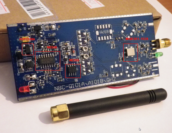
phasenoise has posted his teardown of a cheap GPS Jammer. This GPS jammer generates a 1575.42 Mhz interference to prevent your GPS unit from receiving correct positioning signals.
Generally, “jammers” — which are also commonly called signal blockers, GPS jammers, cell phone jammers, wifi jammers, etc. are radio frequency transmitters that are designed to block, jam, or otherwise interfere with radio communications.
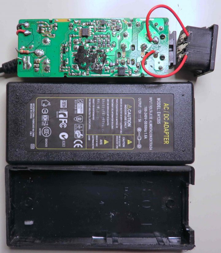
Michael Dunn has done three teardowns of the worst 12V adapters and what he found is interesting.
Yes! Can you believe it? This board used to be in another adapter housing, or more likely, in an end-product. It seems Chinese manufacturing has sunk to a new low: repackaging used and/or surplus power supplies. On the plus side…recycling.