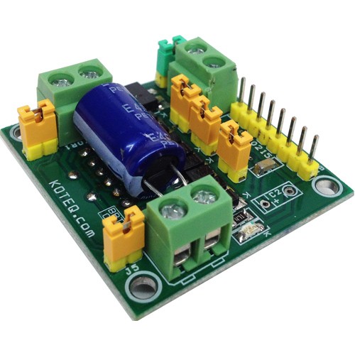
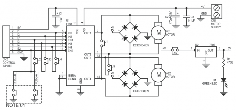
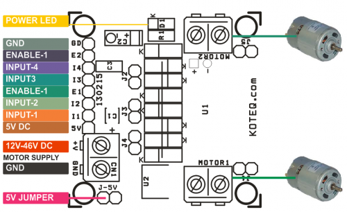
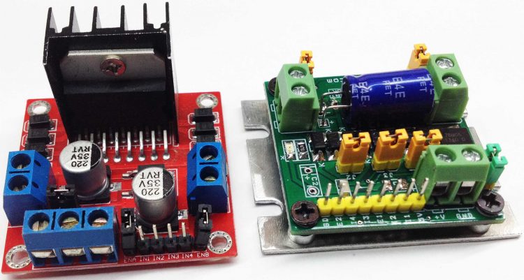
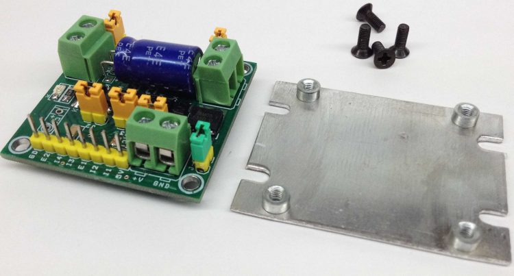
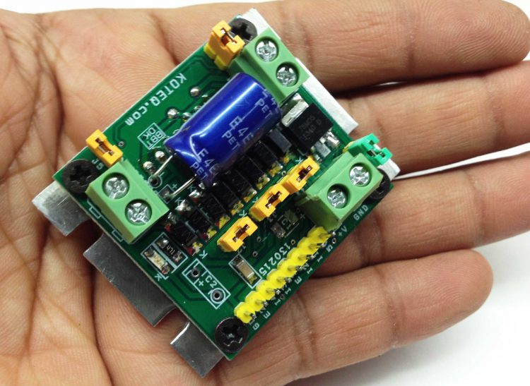
Dual Motor L298 H-Bridge Control project can control two DC motors connected to it. The circuit is designed around the popular dual H-Bridge L298 from ST. This board can be configured to drive a single motor with high current rating also. This can be achieved with the help of jumpers on the board. An onboard 5V regulator can take a maximum of 18V of DC input. Should you wish to drive this board with higher voltage than 18V, you will need to connect a external 5V regulated source to the logic circuit. For this you will need to remove J-5V. This board can fit in any small toy or robot due to small size and very low profile. L298 IC is mounted under the PCB in horizontal position to make board small and low profile to fit any small robot. On board 5V regulator can be used to power up external Micro-Controller board as well as internal logic supply.
Features
Motor supply: 7 to 46 VDC
Open J-5V Jumper if Input Motor Supply is above 18V ( Required External 5V for Logic)
Control Logic Input: Standard TTL logic level
Output DC drive to motor: up to 2 A each (Peak)
On Board 5V Regulator (Close J-5V to Use On Board 5V Regulator)
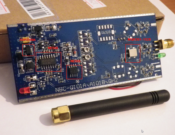
phasenoise has posted his teardown of a cheap GPS Jammer. This GPS jammer generates a 1575.42 Mhz interference to prevent your GPS unit from receiving correct positioning signals.
Generally, “jammers” — which are also commonly called signal blockers, GPS jammers, cell phone jammers, wifi jammers, etc. are radio frequency transmitters that are designed to block, jam, or otherwise interfere with radio communications.
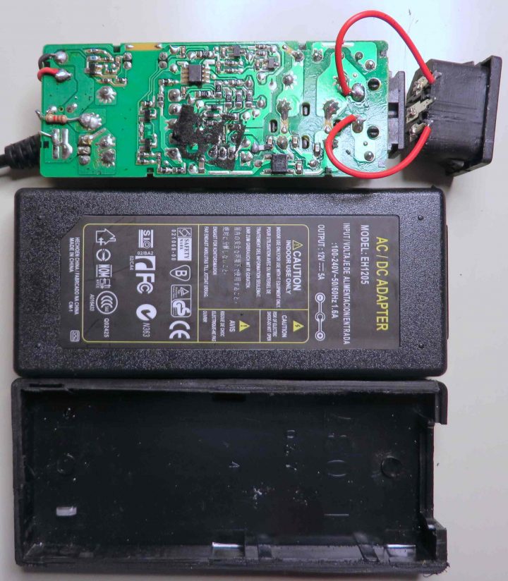
Michael Dunn has done three teardowns of the worst 12V adapters and what he found is interesting.
Yes! Can you believe it? This board used to be in another adapter housing, or more likely, in an end-product. It seems Chinese manufacturing has sunk to a new low: repackaging used and/or surplus power supplies. On the plus side…recycling.
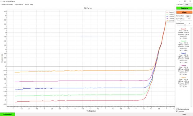
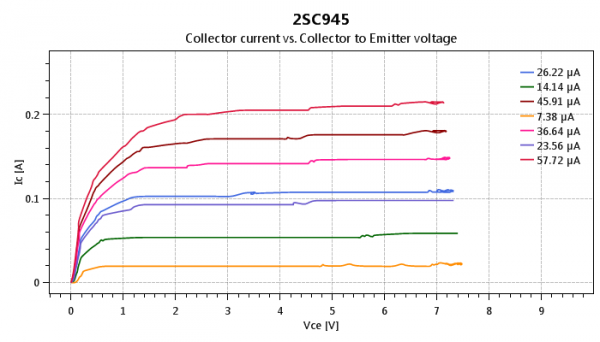
Dilshan Jayakody documented his USB port base NPN transistor curve tracer project:
Curve tracer is an electronic test instrument to analyze the characteristics of transistors and other discrete semiconductors. In this post we construct USB base curve tracer to analyze properties of NPN transistors. This curve tracer is build around Microchip’s PIC18F4550 MCU and it use simple Windows based GUI application to plot captured data of a transistor.
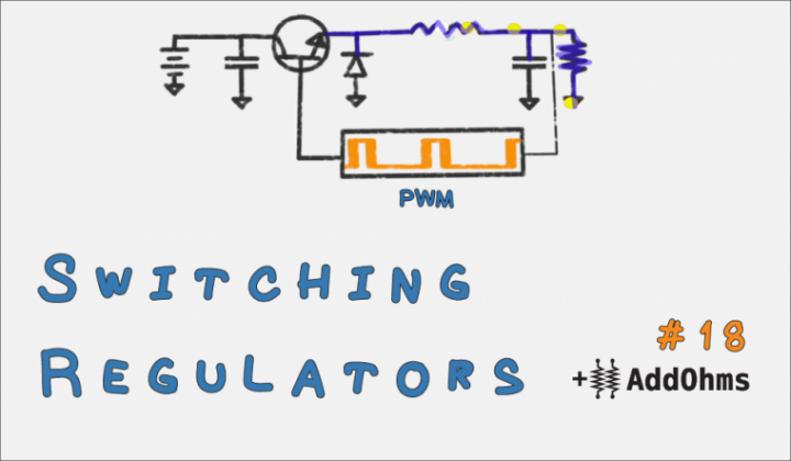
James Lewis @ baldengineer.com discuss about switching regulator types and uses.
A switching voltage regulator is one of my favorite circuits. In school, they were the first circuits I built where I understood how transistors worked. In fact, they were the first circuit I saw an inductor being useful! Switching regulators are incredibly efficient when designed properly. Of course, this detail about design is important.
Basic Switching Voltage Regulator Tutorial – [Link]
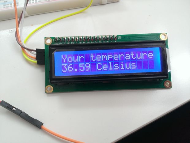
This is a body thermometer using a thermistor sensor, Arduino and LCD display.
I’ve decided to provide a funny Arduino concept thermometer in case its the middle of the night, pharmacies are not working, you are not feeling well and you want to check your body temperature. If you have Arduino by your side, this is a life saver!
Moshe Gerstanhaber @ edn.com provides an simple ADC interface using instrumentation amplifier IC.
Real-world measurement requires the extraction of weak signals from noisy sources. High common-mode voltages are often present even in differential measurements. The usual approach to this problem is to use an op amp or an instrumentation amplifier and then perform some type of lowpass-filtering to reduce the background noise level.
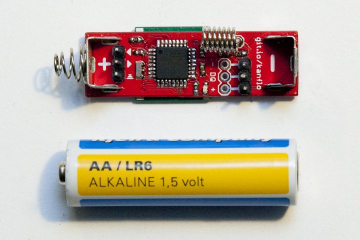
Johan wanted to shrink his Arduino based ISM radio node to fit in an AA battery compartment so AAduino was born.
The AAduino is an wireless Arduino clone the size of an AA battery with Keystone battery terminals rotated 180° to act as positive and negative terminals. It is powered by an ATMega328p and is fitted with an RFM69C companion. There is room for two DS18B20 temperature sensors and an indicator LED.
AAduino – Arduino Wireless in AA form factor – [Link]
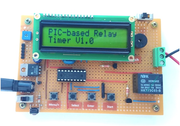
Raj Bhatt shared another project with us. This time is a programmable digital timer with relay switch based on PIC16F628A.
Programmable relays find use in numerous automation applications such as automatic street light control, watering and pump control, HVAC, home automation, power plants automation in industries, etc. This article describes how to build a fully functional, one-channel programmable relay switch using the PIC16F628A microcontroller. It allows you to set both ON and OFF time. The maximum time interval that you can set for on and off operations is 99 hours and 59 minutes. Another interesting feature of this project is it offers cyclic option, which means you can choose to run it in a continuous loop of ON and OFF cycles. The device can be programmed through 4 push switches. The programming menu and device status are displayed on a 16×2 character LCD. The timing resolution of this relay timer is 1 minute. The timer also saves the user inputs to its internal EEPROM so that it can retain these values after any power supply interrupt.