Programmable relays find use in numerous automation applications such as automatic street light control, watering and pump control, HVAC, home automation, power plants automation in industries, etc. This article describes how to build a fully functional, one-channel programmable relay switch using the PIC16F628A microcontroller. It allows you to set both ON and OFF time. The maximum time interval that you can set for on and off operations is 99 hours and 59 minutes. Another interesting feature of this project is it offers cyclic option, which means you can choose to run it in a continuous loop of ON and OFF cycles. The device can be programmed through 4 push switches. The programming menu and device status are displayed on a 16×2 character LCD. The timing resolution of this relay timer is 1 minute. The timer also saves the user inputs to its internal EEPROM so that it can retain these values after any power supply interrupt. Here are the summary of the features that this timer device has:
- Microcontroller powered timer switch
- OFF and ON time setup for the relay operation
- Option for cyclic run
- ON/OFF timing range: 0 to 99 hours and 59 minutes
- 1 minute timing resolution
- Interactive user interface using 4 tact switches and a character LCD
- Buzzer alarm
- On-board +5V voltage regulator
Circuit diagram
The hardware part of this project is very simple. The entire circuit runs off a regulated 5V power supply derived using the popular LM7805 linear regulator chip (Figure 1). To minimize the heat dissipation in the voltage regulator, the recommended input DC voltage to LM7805 is 9V, which can be easily obtained from a DC wall adapter. Diode D1 (1N4001) is used for reverse polarity protection in the circuit. S1 is a slide switch for turning the power supply on and off.
Figure 2 depicts the input and output setup. There are five tact switches in this project: one for microcontroller reset, and four for user inputs. The four input switches are named as Menu/+, Select, Enter, and Start/Stop. Their functions will be described in the software section. The status of the 4 input switches is read by the PIC16F628A microcontroller through ports RA2, RA3, RA4, and RB0. The output LCD is a standard HD44780-based display and is driven in 4-bit mode. The pin assignments for the LCD data and control signals are shown in Figure 2. S2 is another slide switch that allows manual control of the LCD backlight.
The output relay switch is driven through a NPN transistor (2N2222). The project also includes a DC buzzer that beeps when the relay switch changes its status. The relay and buzzer circuits are shown in Figure 3.
The PIC16F628A microcontroller runs at 4.0 MHz using an external resonator. The I/O pins of PIC16F628A, the resonator connection, and the in-circuit serial programmer (ICSP) header are shown in Figure 4.
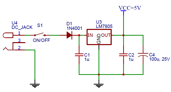
Figure 1. Regulated +5V power supply unit
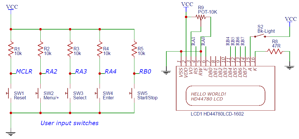
Figure 2. I/O circuit with PIC16F628A pin assignments
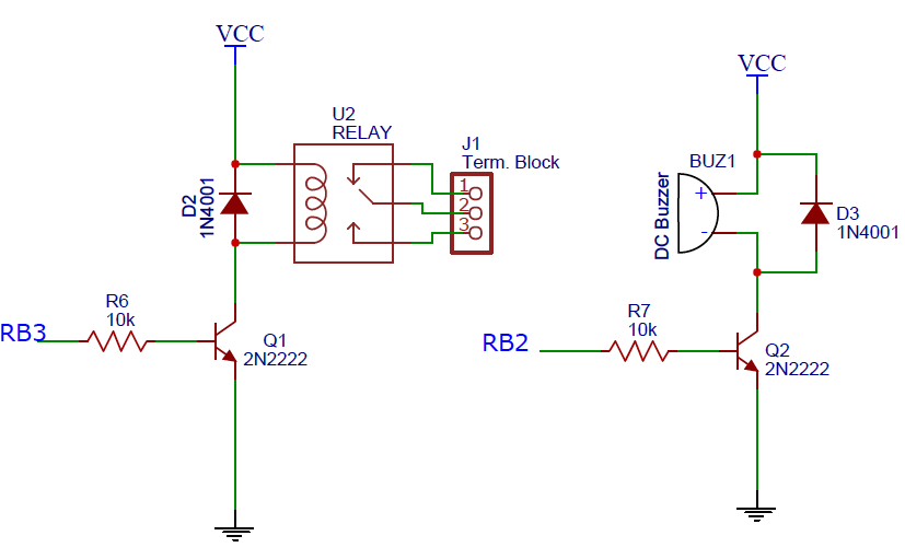
Figure 3. Relay and buzzer control circuit
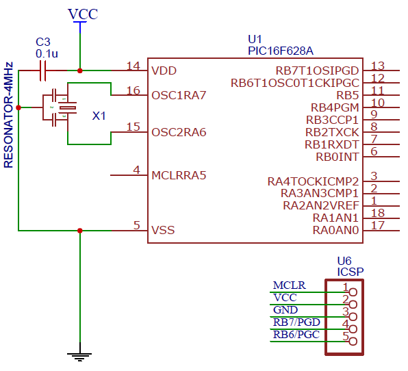
Figure 4. PIC16F628A resonator and ICSP header connections
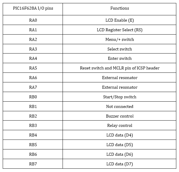
The PIC16F628A pin assignments for the LCD, switches, relay and buzzer circuits are listed in the following table.
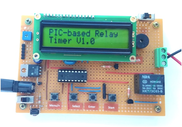
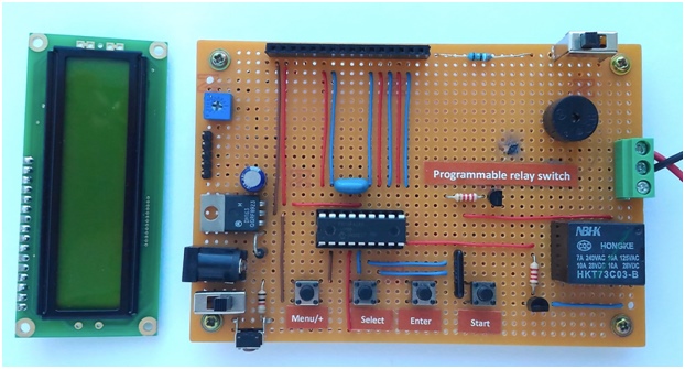
The following figure shows the complete relay timer circuit soldered on a general-purpose prototyping board.
Software
The programmable relay timer gets inputs from the 4 push buttons. Their functions are described as follows:
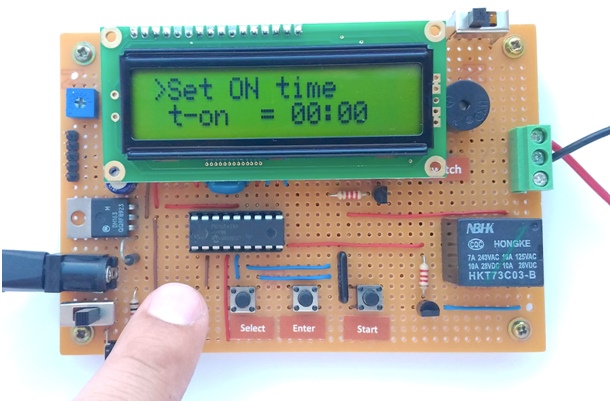
Menu/+ : This button allows you to navigate between various menu options such as ON time setup, OFF time setup, and Cyclic option setup. These options are displayed on the LCD. This button also serves as digit increment during time setup. The time is set in HH:MM format, which gives the minimum value of timing interval to be 1 min.
Select : This allows you to choose a displayed menu option as well as individual hour and minute digits. The selected digit is incremented by 1 when Menu/+ button is pressed.
Enter: When the appropriate hour and minutes are set, pressing the Enter button finalizes the time. The Cyclic option is also entered using this button.
Start/Stop: This push button is to start and stop the timer. If the timer is already on, you can stop it at anytime during its operation by pressing this button.
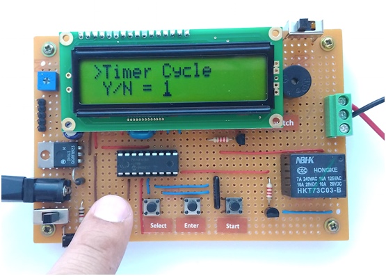
Now let’s see how it works. Suppose, the relay switch is needed to be turned on after 15 minutes for 10 minutes. This means the OFF time is 15 minutes and ON time is 10 minutes. Once the timer is started after entering the above times, the device will be turned on after 15 minutes and remained on for 20 minutes. After that it will be turned off again. If the Cyclic option is selected to 1, the timer will run in a loop and after another 15 minutes of OFF time, the relay will be turned on for next 10 minutes, and so on.
The firmware for this project is developed using mikroC Pro for PIC compiler from mikroElektronika. The time keeping is achieved using the Timer 0 module built inside the PIC16F628A. The Timer0 interrupt is enabled and run with 1:256 prescaler value to create a precise 500 ms (half-second) duration. The colon symbol between HH and MM digits blinks at 1 Hz. The half-second delay is looped 120 times to construct a minute-duration. You can download the complete project files including the source code and compiled HEX file in the attached file.
Photos
The following video shows the timer device in action.
Keynotes:
- The function of the buzzer is to notify the user with a beeping sound whenever the relay is switched on and off.
- In case of power failure, the timer will retrieve the user selected ON and OFF times from the EEPROM. But the timer will be stopped and won’t run until the user presses the Start
- All circuit diagrams used in this project are original and drawn by the author using the EasyEDA schematic editor. EasyEDA is a free online CAD tool for circuit layout, PCB design, and simulation.
Author: Raj Bhatt (electronics enthusiast, and hardware maker, and founder of Embedded Lab; visit my Tindie store)
- Embedded Lab (http://www.embedded-lab.com)
- Visit my Tindie store (https://www.tindie.com/stores/rajbex/)
- Keynotes: EasyEDA (http://www.easyeda.com)