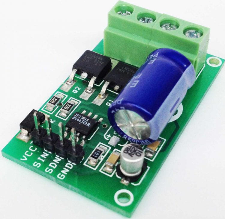
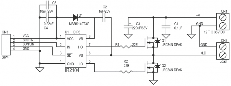
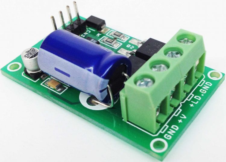
This Half-bridge driver based on IR2104 gate driver IC and N channel Dpak MOSFET , The IR2104 is a high voltage, high speed power MOSFET driver with independent high and low side referenced output channels. HVIC and latch immune CMOS technologies enable ruggedized monolithic construction. The logic input is compatible with standard COMOS or LSTTL output, down to 3.3V logic. A gate IR2104 driver is a power amplifier that accepts a low-power input from a controller IC and produces a high-current drive input for the gate of a high-power transistor such as a power MOSFET. In essence, a gate driver consists of a level shifter in combination with an amplifier.
This drive has many application, ranging from DC-DC power supply for high power density and efficiency, This project simplifies the design of control systems for a wide range of motor applications such as home appliances, industrial drives, DC brushed motors , Brushless motors, fans, Tesla Coil driver, Induction coil driver, LED driver, Halogen Lamp driver.
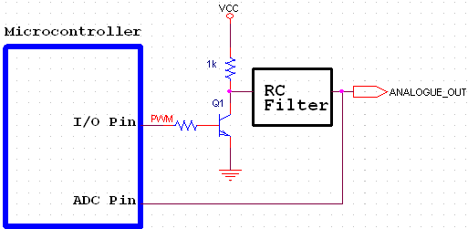
Maurizio @ emcelettronica.com tipped us with his latest article on how to generate analog voltages using a microcontroller.
Many times, designers are faced with the need of generating analogue or analog voltage levels in purely digital circuits. Although the market provides today a very broad range of dedicated digital-to-analogue converters, putting such a device in the schematic has a negative impact on the overall cost of the system.
How-to use PWM to Generate Analog Voltage in Digital Circuits – [Link]
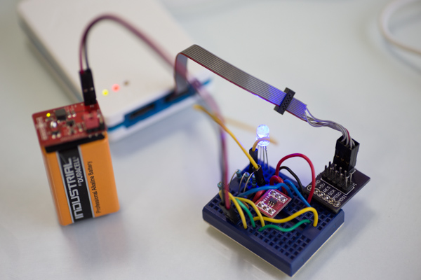
Mahesh @ electronut.in show us how to program these tiny microcontrollers (ATtiny10) with Atmel Studio 7 and make an RGB led to light.
I like Atmel tinyAVRs because they are tiny computers that I can (almost) wrap my head around. The Atmel ATtiny4/5/9/10 are the cheapest in the tinyAVR line, and they come in two packages – SOT23 pictured above, and an even more stupendously small 2mm x 2mm USON package. This article will talk about programming these little chips. Though they may be tiny, they are still quite capable, and the right choice for many projects.
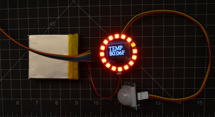
This is an OLED temperature display based on ATmega328p along with a NeoPixel led ring to display different colors depending on temperature.
This is a small temperature display using a OLED with a NeoPixel Ring around it using MQTT on a ESP8266 and sending data to the on board ATmega328p. It will cycle on a timer though environmental data from other nodes in the house. The LEDs represents the temperature based on color to give an idea of the temperature in the home or apartment I also added a PIR to turn off the LEDs when no one is around since this is designed to run off a LiPo battery. The core is running DomotiGA (Home automation core) and Mosquitto (MQTT broker). Part of this project is exploring the ESP8266 and learning MQTT.
Temperature Display with NeoPixel Ring Color – [Link]
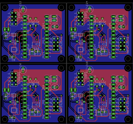
Shantam Raj @ hackster.io discuss about how to panelize PCBs and generate Gerbers on Eagle CAD. In this article he shares his experience and common mistake he made in the process.
I have been working with Eagle for quite some time but never really got a PCB manufactured. almost all the time i used the toner transfer method to make homebrew PCBs. But then i took a project in which i had to use SMD components and i could no longer use toner transfer method because of the limits on resolution of the Laser printer.
Panelizing and Gerber Generation in Eagle – [Link]
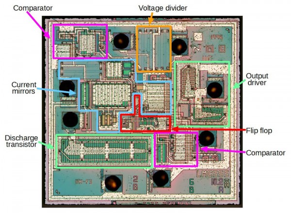
Ken Shirriff wrote an article on reverse engineering the 555 timer chip, He writes:
This article explains how the LMC555 timer chip works, from the tiny transistors and resistors on the silicon chip, to the functional units such as comparators and current mirrors that make it work. The popular 555 timer integrated circuit is said to be the world’s best-selling integrated circuit with billions sold since it was designed in 1970 by analog IC wizard Hans Camenzind[1]. The LMC555 is a low-power CMOS version of the 555; instead of the bipolar transistors in the classic 555 (which I described earlier), the CMOS chip is built from low-power MOS transistors. The LMC555 chip can be understood by carefully examining the die photo.
Reverse engineering the popular 555 timer chip – [Link]
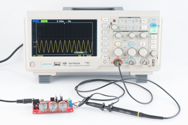
Modern digital oscilloscopes have a great many features that are not apparent to the casual user. By using these “hidden” features, you can save time and get the results you need to get the job done. This is the third installment of useful hints for extending the effectiveness of your digital oscilloscope.
Sparkfun has compiled a list of resources about everything you need to design for manufacture an electronic product.
Let’s be frank: We’ve made a lot of mistakes over the years. In the ongoing pursuit of better-designed PCBs, we’ve dealt with tons of screw-ups, from boards with ill-arranged traces to boards with…no traces at all, actually, and a host of others. Fortunately, by now we feel like we’ve gotten a pretty solid handle on a largely-error-free design for manufacturing process, and we want to help you avoid some of our past mistakes.
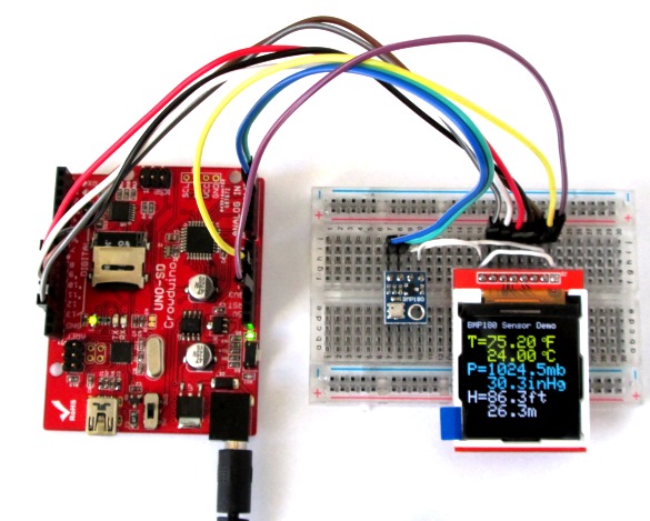
Raj from Embedded Lab has posted a comprehensive tutorial on how to use BMP180 for temperature, pressure, and altitude measurements.
The BMP180 is a new generation digital barometric pressure and temperature sensor from Bosch Sensortec. In this tutorial, we will briefly review this device and describe how to interface it with an Arduino Uno board for measuring the surrounding temperature and pressure. We will also discuss about retrieving the sensor altitude from its pressure readings.
Using BMP180 for temperature, pressure and altitude measurements – [Link]
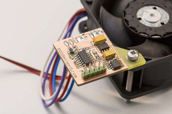
Lukas Fassler from Soldernerd has written up documentation on his DIY fan controller project:
I’m currently mainly working on my new anemometer design but once in a while I get distracted. For example when my Keysight E3645A lab power supply was making so much noise that I could hardly concentrate. That’s when the idea of this fan controller was born.