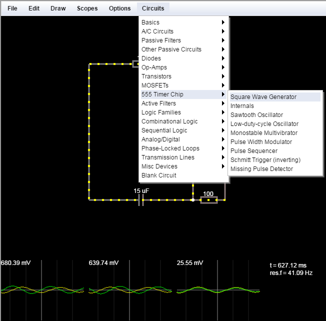
Iain Sharp build this port of online Circuit Simulator based on Paul Falstad’s simulator, however Sharp’s version is built using HTML5 and requires no plugin to run. Think of it like animated Fritzing circuits, with a slew of pre-built circuits and components available for tinkering with.
educ8s.tv wanted to take a look at this tiny board for a long time. It is very small size, it is low cost and it uses a different processor than the Arduino boards. It uses the ATTiny 85 microcontroller chip, which can operate at a frequency up to 20Mhz. It has 8Kb of flash memory, 512bytes of RAM memory and 6 I/O pins 2 of which can implement the I2C protocol. It is very small in size and has low power requirements. We can program it using the Arduino IDE, which makes things so much easier! I got this tiny board with a USB interface in order to be easier to program. You can find a link for this ATtiny85 board in the description of the video.
educ8s.tv wanted to test if the ATtiny85 board is a good option for simple projects and if we achieve longer battery life with this board that a standard Arduino mini. Let’s find out together.
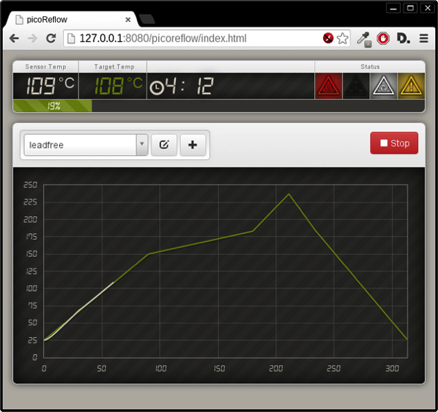
Here is a great Raspberry Pi based Reflow oven controller from “apollo-ng” on GitHub. You can edit your temperature curve on your browser and Rasberry Pi controls the solid state relays and fan.
Turns a Raspberry Pi into a cheap, universal & web-enabled Reflow Oven Controller. Of course, since it is basically just a robot sensing temperature and controlling environmental agitators (heating/cooling) you can use it as inspiration / basis when you’re in need of a PID based temperature controller for your project. Don’t forget to share and drop a link, when you do.
How to Control a Reflow Oven with Raspberry Pi – [Link]
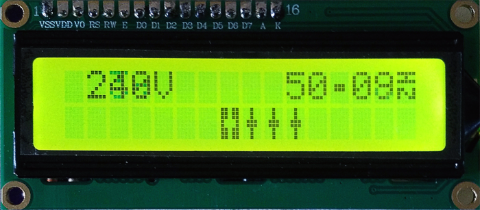
This project is about an accurate mains frequency meter that has a bar-graph displaying the relative deviation from nominal frequency. It can work with 50Hz and 60Hz systems.
An article by Dieter Laues in the February 2012 issue of Elektor inspired me to get my soldering iron out. The article described how by measuring the frequency of the mains electricity supply in any socket, the relative load across the entire electricity network could be determined
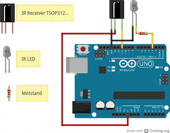
Øyvind Nydal Dahl show us how to use an IR remote control with Arduino. For this purpose he connects a TSOP312 and an IR LED to Arduino and goes in detail on the sketches.
In this tutorial I am going to show you exactly how to make an Arduino remote control. You can use this project to combine functions from different remote controls and make your super-awesome dream remote control!
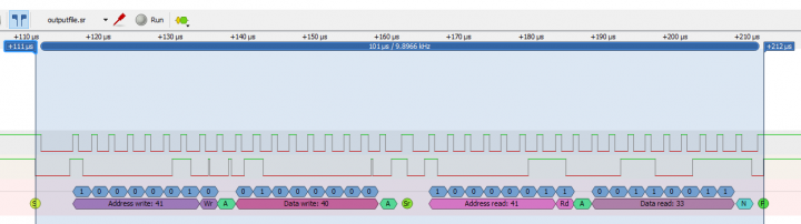
Make your own logic analyzer using BeagleBone board.
Software is where the magic happens. There is a pre-made image for the BeagleBone with everything loaded and configured to use the BeagleLogic. It’s a recent image based on Debian instead of the older Armstrong builds. The nice thing is that it doesn’t flash the eMMC so you can leave your existing setup alone and just pop in the SD card when you need your logic analyzer. Which is another reason that makes it a good option. I can still use the BeagleBone hardware for other projects and not keep it collecting dust in between uses.
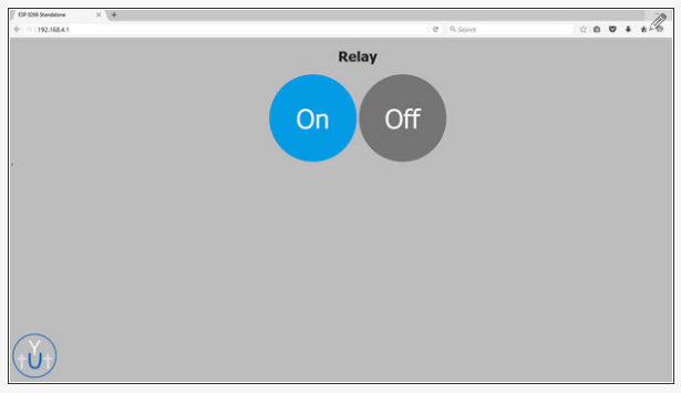
In this tutorial you will learn how to use ESP8266 in standalone mode to control a relay via Web-UI. The ESP broadcasts its own SSID and there is no need to connect to a router.
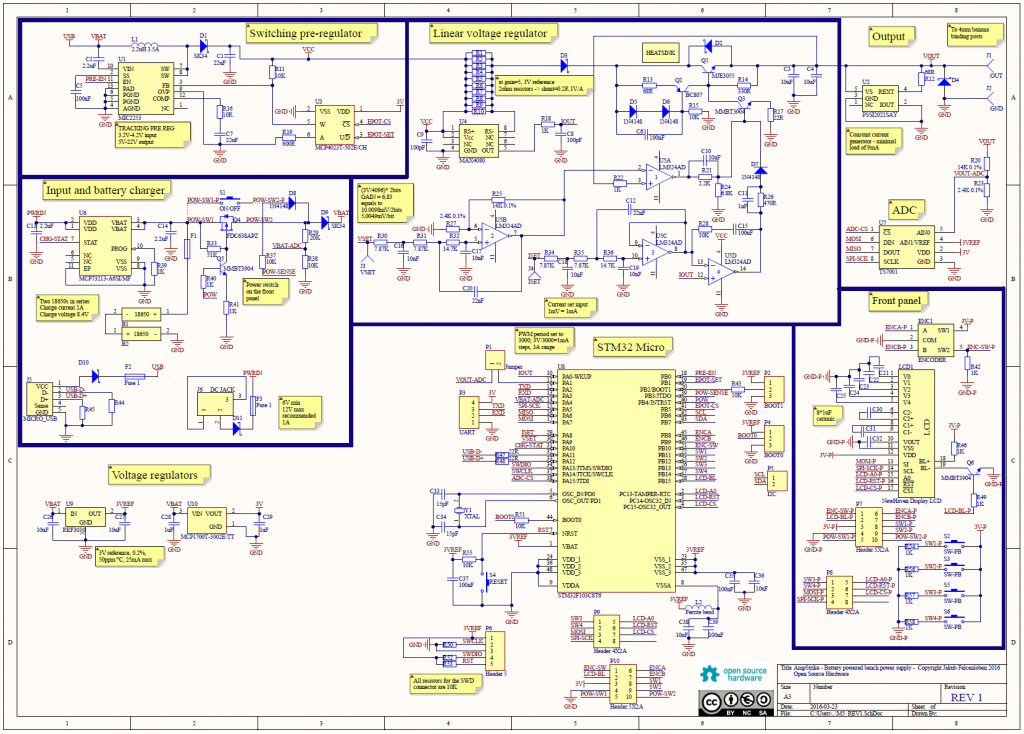
This is a small bench power supply that is powered by two lithium-ion batteries. The project was inspired by Dave Jones from EEVblog but the design is completely mine. The voltage range is 0-20V regulated in 10mV steps and maximum current is 1A with current limit set in 1mA steps.
The power supply runs on a linear voltage regulator built on discrete components. The design of the linear regulator was inspired by the user Amspire from the EEVblog forum. The basic idea is that the Q1 pass transistor and U5A op amp act in a classic voltage regulating loop. U5A gets feedback from the output voltage and acts on Q1 in such a way that the output voltage equals the reference voltage on the inverting input. U5D acts as a comparator and switches the base of Q1 low to set the output voltage to 0V. It acts as a current limiter which is quickly switching on and off the output to maintain the set current limit.
AmpStrike – Battery Powered Bench Power Supply – [Link]