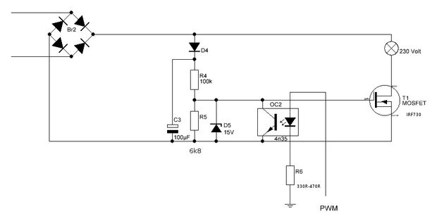
diy_bloke @ instructables.com has designed an AC PWM dimmer for Arduino:
Over 3 years ago, I published a simpel TRIAC AC dimmer for the arduino. That proved to be a very popular design. Yet in spite of the simplicity of the circuit the software needed was a bit complicated as it needed to keep track of the zero crossing of the AC signal, then keep track of the time and then finally open the TRIAC. So to avoid letting the arduino just wait for most of the time, an interrupt and a timer were necessary.
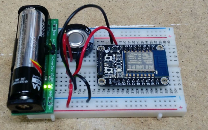
A single AA battery provides voltages of 5V or 3.3V for hardware prototyping.
This tiny board allows you to bring the power to your project, and not the other way around. Bring your micro to the sensor without running wires! A single AA battery is used to provide breadboard power of 5V or 3.3V (or other voltages by tuning the feedback resistors). A boost regulator provides the voltage.
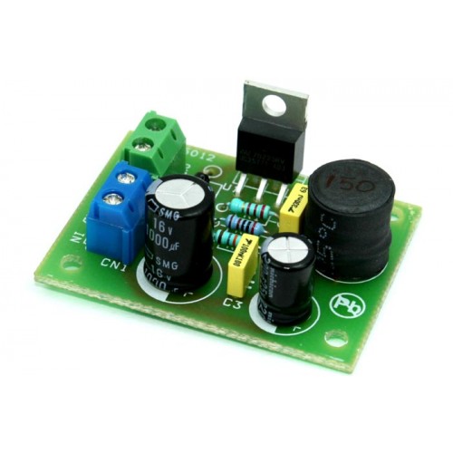
Step up DC-DC converter is based on LM2577-ADJ IC, this project provides 12V output using 5V input, maximum output load 800mA. The LM2577 are monolithic integrated circuits that provide all of the power and control functions for step-up (boost), fly back, and forward converter switching regulators. The device is available in three different output voltage versions: 12V, 15V, and adjustable.
Requiring a minimum number of external components, these regulators are cost effective, and simple to use. Listed in this data sheet are a family of standard inductors and fly back transformers designed to work with these switching regulators. Included on the chip is a 3.0A NPN switch and its associated protection circuitry, consisting of current and thermal limiting, and under voltage lockout. Other features include a 52 kHz fixed-frequency oscillator that requires no external components, a soft start mode to reduce in-rush current during start-up, and current mode control for improved rejection of input voltage and output load transients.
Features
Requires Few External Components
Input 5V DC
Output 12V DC
Output Load 800mA
Current-mode Operation for Improved Transient Response, Line Regulation, and Current Limit
52 kHz Internal Oscillator
Soft-start Function Reduces In-rush Current During Start-up
Output Switch Protected by Current Limit, Under-voltage Lockout, and Thermal Shutdown
Step up DC-DC converter is based on LM2577-ADJ IC, this project provides 12V output using 5V input, maximum output load of 800mA. The LM2577 are monolithic integrated circuits that provide all of the power and control functions for step-up (boost), fly-back, and forward converter switching regulators. The device is available in three different output voltage versions: 12V, 15V, and adjustable.
Requiring a minimum number of external components, these regulators are cost-effective, and simple to use. Listed in this data sheet are a family of standard inductors and fly-back transformers designed to work with these switching regulators. Included on the chip is a 3.0A NPN switch and its associated protection circuitry, consisting of current and thermal limiting, and under voltage lockout. Other features include a 52 kHz fixed-frequency oscillator that requires no external components, a soft start mode to reduce in-rush current during start-up, and current mode control for improved rejection of input voltage and output load transients.
Features
Requires Few External Components
Input 5V DC
Output 12V DC
Output Load 800mA
Current-mode Operation for Improved Transient Response, Line Regulation, and Current Limit
52 kHz Internal Oscillator
Soft-start Function Reduces In-rush Current During Start-up
Output Switch Protected by Current Limit, Under-voltage Lockout, and Thermal Shutdown
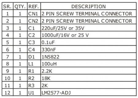
PCB Dimensions: 45.72 x 34.29 mm
Project is based on LM2577-ADJ IC for flexibility to obtain other output voltages by changing value of feedback resistors R2 and R3
Output Voltage Formula V Out=1.23V (1+R2/R3) (Read DataSheet for more information about Inductor value, Capacitor, Feedback resistors, Output current and voltage)
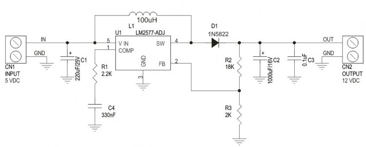
Schematic
How It Works
LM2577 turns its output on and off at a frequency of 52 KHz, and this creates energy in the inductor L1.
When the NPN switch turns on, the inductor current charges up at a rate of vin/L1, storing current in the inductor. When the switch turns off,, the lower end of the inductor flies above Vin, discharging its current through diode into the output capacitor at rate of (Vout-Vin)/L1. Thus energy stored in the
inductor during the switch on time is transferred to the output during the switch off time. The output voltage is controlled by amount of energy transferred which , in turn, is controlled by modulating the peak inductor current. This is done by feeding back portion of the output voltage to the error amp, which amplifies the difference between the feedback voltage and a 1.23V reference. The error amp output voltage is compared to a voltage proportional to the switch current ( ie., inductor current during the switch on time)
The comparator terminates the switch on time when the two voltages are equal, thereby controlling the peak switch current to maintain a constant output voltage.
MEMSIC has announced the MMC3630KJ magnetometer that integrates a monolithic 3-axis AMR (anisotropic magnetoresistive) sensor and a signal conditioning ASIC into a 1.2 × 1.2 × 0.5-mm BGA package.
According to MEMSIC, devices in the series offer the ability to deliver a magnetic sensitivity in a range of ±30 Gauss and achieve a noise level that is five times better than other technologies.
The new sensor aims wearables and smartphones due to small size and low energy consumption. Device features include self-degaussing and a power-saving interrupt function.
MMC3630KJ – Magnetic sensor in BGA package – [Link]
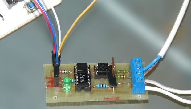
diy_bloke @ instructables.com has build an arduino controlled triac light dimmer and describes the circuit and software used to achieve that.
It becomes a bit more tricky if one wants to dim a mains AC lamp with an arduino: just limiting the current through e.g. a transistor is not really possible due to the large power the transistor then will need to dissipate, resulting in much heat and it is also not efficient from an energy use point of view.
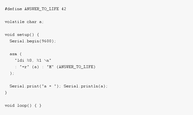
ucexperiment.wordpress.com has published a series of tutorials on how to use assembly language on Arduino. This can be pretty helpful if you want to do some advantaged coding on Arduino.
An inline assembly statement is a string which specifies assembler code. The string can contain any instructions recognized by the assembler, including directives (we will not discuss assembler directives here). GCC does not parse the assembler instructions and does not know what they mean or even whether they are valid. Multiple assembler instructions can be placed together in a single asm string.
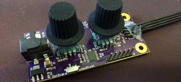
Thomas Gonnot has published a RGB LED Strip Controller based on STM32F0 microcontroller. The controller is able to power NeoPixel and DotStar protocol RGB LEDs.
A simple controller for a RGB LED strip, with independent control of color and intensity.
The design is based on a simple STM32F0 microcontroller. It can handle NeoPixel and DotStar protocols, and the power supply can vary from 5V to 15V.
Firmware available at https://github.com/fearedspark/RGB_LED_Strip_Controller
OSH park permalink: https://oshpark.com/shared_projects/Fg2xQq0t
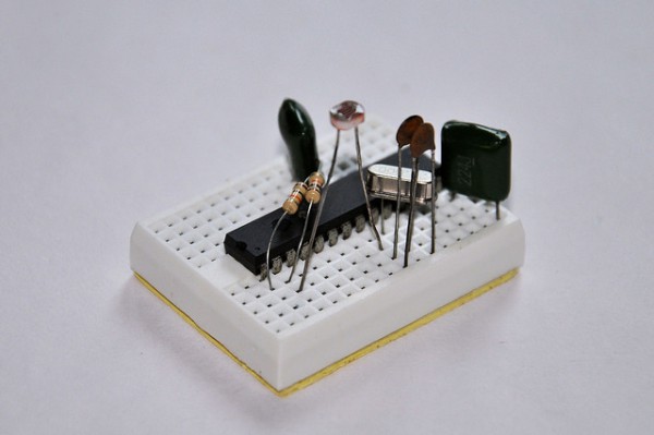
Dilshan Jayakody build a auto monitor brightness controller that adjusts your monitor brightness according to lighting conditions. He writes:
The sensor unit of this system is build around PIC18F2550 8-bit microcontroller. To measure the light level we use LDR with MCU’s inbuilt ADC. The control software of this unit is design to work with Microsoft Windows operating systems and it use Windows API’s DDC/CI related functions to control the monitors/display devices.