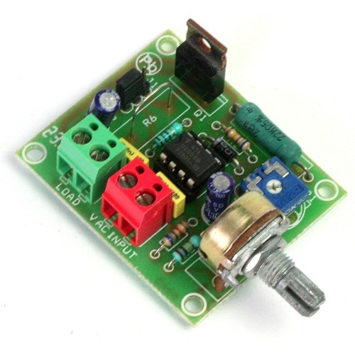
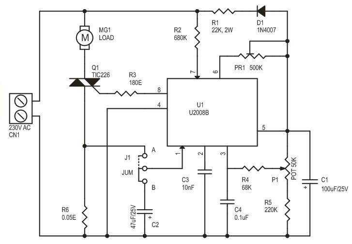
This is a low cost, current feedback phase control AC motor driver based on U2008 IC. The U2008B is designed as a phase control circuit in bipolar technology. It enables load-current detection as well as mains-compensated phase control. Motor control with load-current feedback and overload protection are preferred applications.
Specifications
Supply Input: 230V AC
Load: up to 500W (Triac Requires Heat sink for Higher Load)
Jumper J1 Selection: A-Load Current Compensation or B-Soft Start
PR1: Preset for Phase Control ( Ramp Current Adjustment)
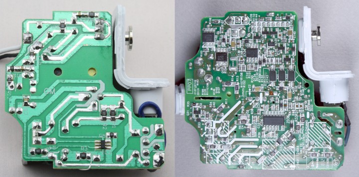
Ken Shirriff @ righto.com has done a detailed teardown of a counterfeit macbook charger and show us the difference from a genuine one and why this can be dangerous. He writes:
What’s inside a counterfeit Macbook charger? After my Macbook charger teardown, a reader sent me a charger he suspected was counterfeit. From the outside, this charger is almost a perfect match for an Apple charger, but disassembling the charger shows that it is very different on the inside. It has a much simpler design that lacks quality features of the genuine charger, and has major safety defects.
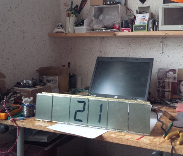
Pierre Muth build a nice big clock using 3″ 7-segment LCD displays. The clock is driven by a PIC18F87K90 and a few other components are used. He writes:
We need clocks. Once you have passionate activities which absorbs all your attention, if you want to keep contact with the social society surrounding you, it’s crucial to know when we are.
BIG Clock Made From Six 3″ 7-Segment LCDs – [Link]
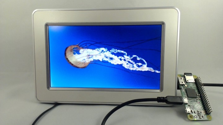
Francesco @ garagetech.tips show use how to use the Raspberry Pi Zero to build a digital frame. Actually he show us how to use it as a USB storage device on an existing digital frame.
My friends at Tangible Interaction sent some electronic whiteboard hardware to take apart. In this video I’ll start to look at the transmitters, receivers, and communication protocol.
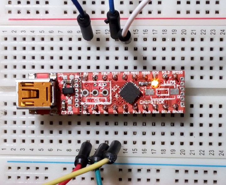
The ChipStick design has the following features:
MSP430FR2433 with 15.5K FRAM and 4K SRAM
External SRAM or FRAM device connected via SPI on USCI B0
CH340G USB to serial converter IC on detachable section of board
3V3 voltage regulator
Reset Switch and User LED
20 Pin DIL footprint to allow insertion into G2 Launchpad socket
Programmable by SBW or BSL
ChipStick – A small scale experimental Forth machine – [Link]
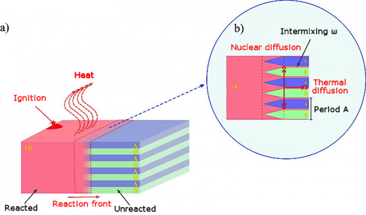
Thijs Beckers @ elektormagazine.com writes about a new experimental method of connecting electronics components together using a laser beam.
Researchers from the University of Saarland have, together with colleagues from Helsinki, discovered a new material which can connect electronic components together using a chemical method. Multiple very thin layers (1000x thinner than a human heir) of aluminum and ruthenium are placed on top of each other. When an intense laser beam is pointed at it, a large amount of heat is released in the nanometer thin layer and a homogeneous layer of ruthenium-aluminide is formed.
This brief heat can reach a temperature of 2000 °C. With this, components close together can be connected to each other without the addition of solder. The ruthenium-aluminide forms a layer between the components, just like solder does.
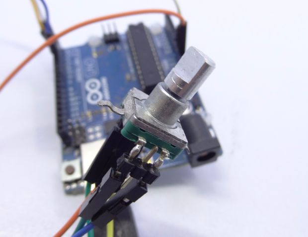
Here is a nice tutorial on how to use rotary encoders with Arduino. Example code is included.
I wanted to use a low cost rotary encoder as an input mechanism for one of my upcoming projects and was initially bewildered by the code options available to take readings from the rotary encoder and determine how many “detents” or cycles the encoder had clicked past and in what direction.