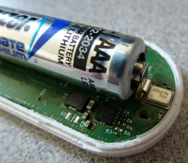
Brian Dipert @ edn.com has done a teardown on Amazon’s dash button and shows the parts inside.
How much hardware was Amazon able to squeeze into such a diminutive bill-of-materials budget, or perhaps more accurately, how much are Amazon and its consumable-supplier partners subsidizing the initial hardware cost in the hope of plenty of future generated profits? Let’s find out.
Teardown: Amazon Dash Button keeps you connected – [Link]
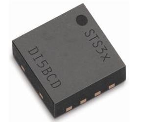
Housed in a tiny 8-pin DFN package, the STS31 digital temperature sensor from Sensirion guarantees accuracy to within ±0.3°C over a temperature range of -40°C to +90°C. A low-cost version, the STS30 achieves the same accuracy over a temperature range of 0°C to +65°C. Both devices are only 0.9 mm high and occupy a footprint of 2.5 × 2.5 mm.
Sensirion Tiny sensor hones temperature accuracy – [Link]
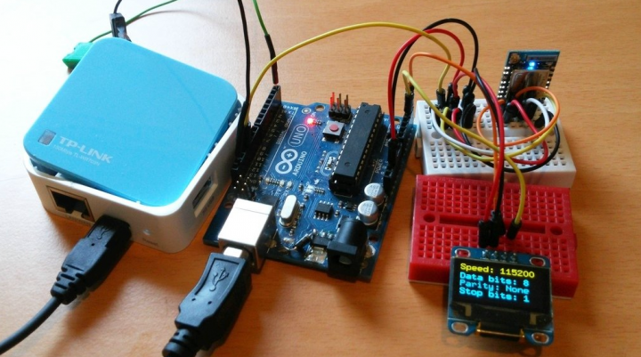
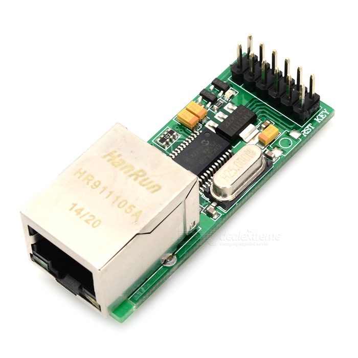
This tutorial shows how to connect Arduino to the TX line (of a router, RPI) and display serial data on smartphone over WiFi.
Arduino listens for serial port communication on its hardware serial port. Then it sends every received line of data trough software serial port to ESP8266. ESP8266 puts every received line of data into circular buffer. ESP8266 also runs code for webserver and a website which pools the buffer for new data and displays it on the website. (Sadly there is no websockets support for ESP8266.) To see this serial data all you have to do is open the website (IP) on your smartphone and enable javascript.
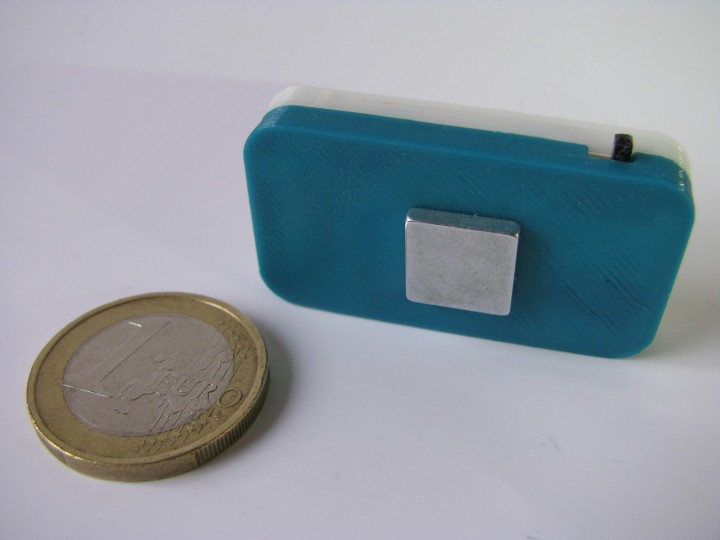
With the help of this wearable device you can improve your posture as it will remind you whenever you slouch. The device is based on ADXL335 accelerometer and Attiny85 microcontroller and a vibration motor will get you notified.
Posture sensors/monitors have been a recurring theme on this blog. They are supposed to remind you of your posture and prevent you from slouching, which can be a cause for back pain and headaches.While my previous sensors were either fixed to a chair or desk, this time I wanted to create a wearable version, that would allow for free movement. As always, one of the main goals was to make this project cheap and easy to reproduce.
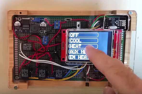
asheville makers @ instructables.com has posted a Wifi enabled thermostat that can be programmed via a touch screen display or via the internet.
This Instructable explains about how I built WiFi enabled thermostats for my home. The thermostats are programmable with 6 different time periods during the day, although increasing that to any arbitrary number would be fairly trivial.
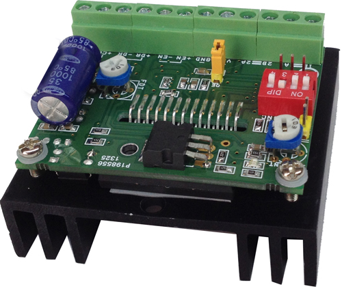
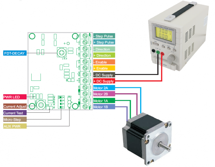
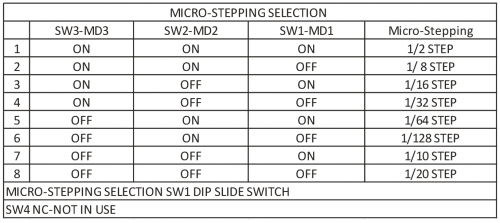
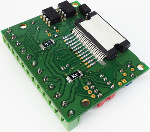
The Project is based on LV8727E IC from ON Semiconductor. The LV8727 is a PWM current-controlled micro step bipolar stepping motor driver. This driver can provide eight ways of micro step resolution of 1/2, 1/8, 1/16, 1/32, 1/64, 1/128, 1/10, 1/20, and can drive simply by the step input. This Bipolar Driver works with supply input 9V to 36V (Replace L317 with L317HVT for supply input up to 45V DC). Load current up to 4Amps.
Features
Supply 9V to 36V DC (Replace L317 with L317HVT for Supply up to 45VDC)
Load Current Up to 4Amps
Inputs: Step Pulse, Direction, Enable
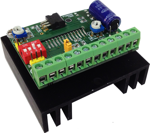
Micro-Stepping: 4 Way DIP Slide Switch
On Board Power Indication
On Board L317 for 5V DC Regulator
Current Adjust Preset
4A Bipolar Stepper Motor Driver Based on LV8727E – [Link]
The Project is based on LV8727E IC from ON Semiconductor. The LV8727 is a PWM current-controlled micro step bipolar stepping motor driver. This driver can provide eight ways of micro step resolution of 1/2, 1/8, 1/16, 1/32, 1/64, 1/128, 1/10, 1/20, and can drive simply by the step input. This Bipolar Driver works with supply input 9V to 36V (Replace L317 with L317HVT for supply input up to 45V DC). Load current up to 4Amps.
Features
Supply 9V to 36V DC (Replace L317 with L317HVT for Supply up to 45VDC)
Load Current Up to 4Amps
Inputs: Step Pulse, Direction, Enable
Micro-Stepping: 4 Way DIP Slide Switch
On Board Power Indication
On Board L317 for 5V DC Regulator
Current Adjust Preset
Over Current protection
Thermal Shutdown
FDT Adjust Preset (DECAY Setting)
Single-Channel PWM current control stepping motor driver.
Output Current 4Amps
Micro Stepping 1/2,1/8,1/16,1/32,1/64,1/128,1/10,1/20 Step are selectable.
Advance the excitation step with the only step signal input
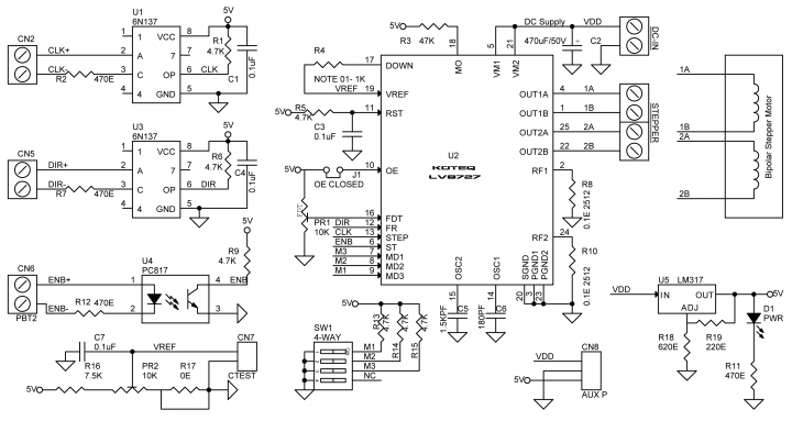
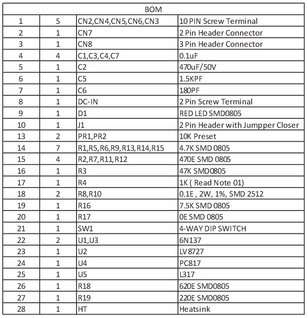
Schematic
Output Current Settings (PR2 Preset Constant Current Setting )
Current Output= (VREF/3)/0.1E (Shunt Resistor R8, R10)
Example: (VREF 0.9V/3)/)0.1E=3Amps
Enable (Stand-by function)
When enable input is high the ST pin is at low levels, The IC enters stand-by mode, all logic is reset and output in turned off
Keep Enable input low (No Signal Input at Enable) for Normal operations, Apply 5V at disable the drive
Jumper-J1 Output Enable ( J1 Closed for Normal Operation)
Jumper Open put the output forced off and goes to high impedance. However the internal logic circuits are operating, so excitation position proceeds when the STP is input, when J1 close, the output level conforms to the excitation position proceed by the step input.
FDT DECAY mode setting (PR1-Prest)
Current DECAY method is selectable as shown below by applied voltage to the FDT pin.
3.5V to 5V Slow DECAY
3.1V to 3.5V Inhibited Zone
1.1V to 3.1V or Open Mixed DECAY
0.8V to 1.1V Inhibited Zone
0 to 0.8V Fast DECAY
Note: It is not recommended to change DECAY method during Motor operation.
Note 01 DOWN output Pin
This pin is turned ON when no rising edge STEP between the input signals. This pin used to set the holding current when motor at HOLD state. Its help reducing the current when motor is not moving and it’s in Holding position.
R4 is associated to control the holding current when motor is in HOLD State, value of R4 to be calculated as per Input Ref voltage, and required holding current, see below formula to calculate the R4
Down Output OFF: VREF=5VXR2/(R1+R2)=0.741V
Down Output On: VREF=5VXR2 (R2IIR4)/(R1+(R2IIR4)=0.126V
Note02 R1 and R2 Divide PR2 and R4=1K
CN8 : 3Pin Header Connector
Auxiliary Power output 5V DC, GND, VDD-Supply Voltage
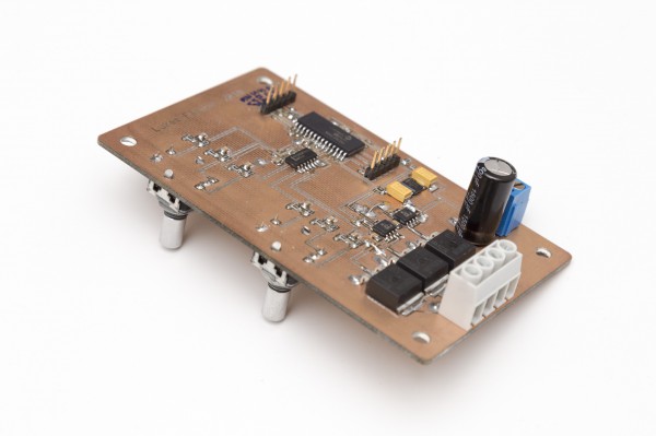
Lukas Fassler has designed and built a PWM dimmer for RGB LED:
In my last post I’ve described the design and construction of my LED dimmer project. This project here is similar but a bit more involved. It controls RGB LEDs so it can not only change the brightness but also the color of the light. Instead of a simple pot it used a pair of rotary encoders with push buttons. One controls the brightness, pushing its button turns the light on or off. The other changes the color, pushing its button toggles between color and white.
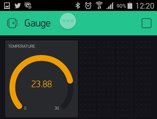
maroelawerner @ instructables.com has a tutorial on how to display temperature data on an Android or iOS device using Arduino and Blynk app.
In this Instructable I am going to attempt to show you how to put together a little project to use the Blynk app (optainable at http://www.blynk.cc/) to display the temperature remotely on a iOS or Android device.
I came across an posting on my Google+ where somebody required some help with this. It looked interesting, so I decided to have a try myself.
Arduino DS18B20 Thermometer on iOS or Android – [Link]
Maurizio @ dev.emcelettronica.com has tipped us with his latest article on how to implement embedded Ethernet on any mcu. The article shows the basic principle of Ethernet implementation.
Usually We need embedded systems inside devices, particularly the so-called intelligent devices, to communicate with a command/control/administrative center. Typical such situations could be a remote security camera that can send you video clips when queried, an embedded system that can send status when checked through a web browser or a vending machine that is capable of sending an email when service is required.