Bob @ robertgawron.blogspot.com has posted a Geiger-Muller project that can be used with Arduino or any other microcontroller board.
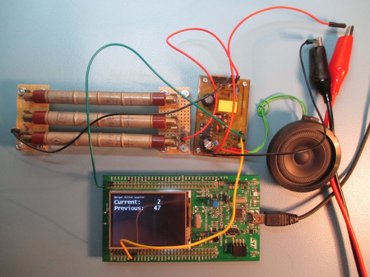
The Geiger–Müller counter is a relatively simple tool to measure ionizing radiation. To increase sensitivity, construction presented here contains three (instead of one as usually) soviet STS-5 lamps. This is important for measurements of natural sources of (low) radiation like soil, rocks (an article about my trip with Geiger–Müller counter on Śnieżka mountain).
Geiger–Müller counter that works with Arduino – [Link]
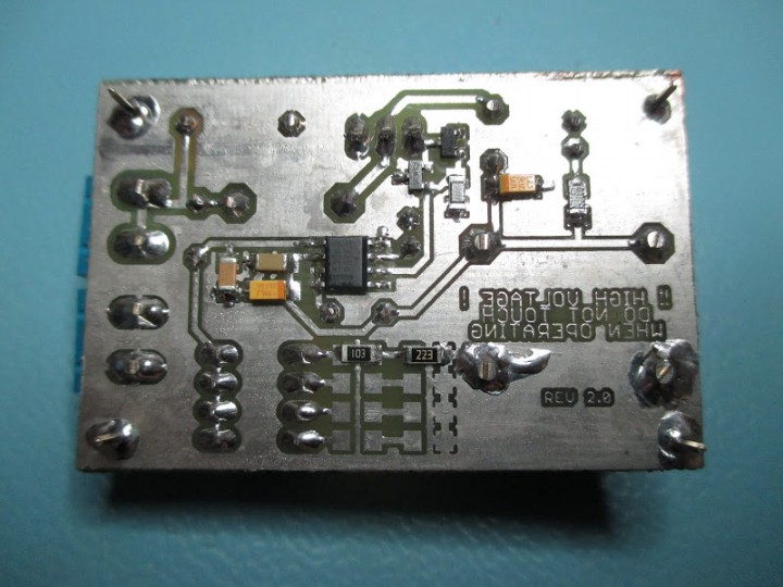
Bob has tipped us with his latest project. It’s a 5V to 400V DC-DC Converter based on MC34063 IC and can be used in various projects such as Geiger–Müller counters.
A small and cheap 5V/400V DC/DC converter can be useful in many DIY projects, e.g Geiger–Müller counters. I will present here one of such DC/DC converter based on popular MC34063 chip in step-up configuration.
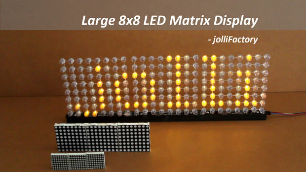
jollifactory @ instructables.com has published a large 8×8 LED Matrix Display which is driven by a MAX7219 and Arduino.
For this project, we will be building a single color large LED matrix display which is made up of a few large 8×8 LED matrix modules daisy-chained together. Each of these 8×8 LED matrix modules is around 144mm x 144mm in size.
In this video we learn how to use this 8×8 RGB LED matrix. This matrix is using the WS2812 driver and it is great, because each LED is individually addressable. Only one microcontroller pin is required to control all the LEDs, and you get 24 bit color for each LED.
8×8 RGB Led Matrix with WS2812 driver with Arduino Uno – [Link]
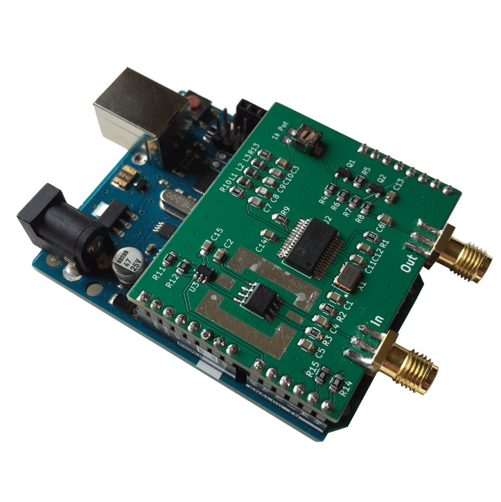
Brett Killion has published his Arduino shield a Network Analyzer on an Arduino Shield which covers from 0-72MHz.
The network analyzer shield uses an Analog Devices AD9851 DDS chip clocked at 180MHz which will output a sine wave at any frequency from 0Hz and 72MHz. The DDS output is filtered with a Butterworth LPF and then passed to a two transistor amplifier. The shield will output approximately 0dBm (maybe 1-2dBm if you turn the Pot up; may get distortion, though) into 50 Ohms. The output and input connectors are SMA. The power detector is an Analog Devices AD8307. It’s inputs are terminated with a 50 Ohm load. There is no filtering on the input of the power detector so the chip is responsive from very low frequencies all the way up to 500MHz.
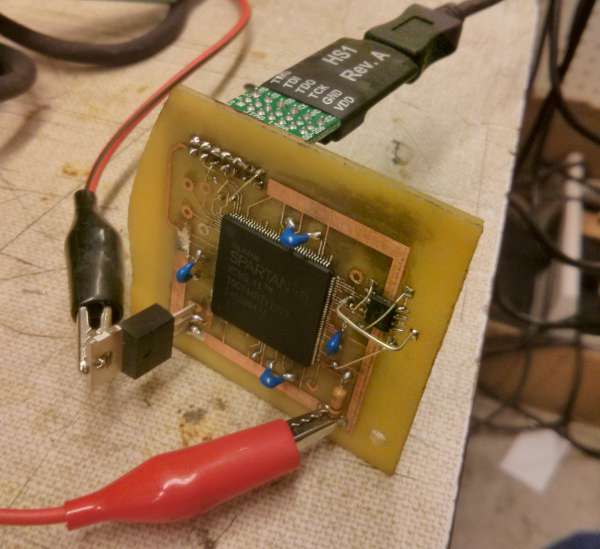
TC-Engineering has documented their efforts to program a Spartan 6 FPGA using a DIY PCB. The hardware part and software are discussed on the link below.
I’ve been thinking about building stuff with FPGA’s for a while, and usually get turned away because FPGA’s are considerably harder to implement than microcontrollers since they have no on-chip memory. It is necessary to re-program the gates every time they power up, which requires an external flash memory chip. There aren’t great references online for the DIY community, so I figured I’d post how to get this working. Not using dev boards opens a world of opportunities, so I’m a proponent of not using Arduino’s and their FPGA equivalent for too long (sure, they’re good to get started with, but don’t become dependent)
Many a times equipment at workstations remains switched on unnoticed. In this situation, these may get damaged due to overheating. Here is an add-on device for the workbench power supply that reminds you of the power-on status of the connected devices every hour or so by sounding a buzzer for around 20 seconds. It also has a white LED that provides good enough light to locate objects when a main fails.
Here, IC NE555 (IC1) is wired as an astable multivibrator, whose time period is set to around six minutes using resistors R1 and R2, preset VR1 and capacitor C1 for sounding the buzzer every hour. The output of IC1 is fed to the clock input of IC CD4017 (IC2). Capacitor C3 and resistor R3 provide power-on-reset pulse to IC2. When power to the circuit is switched on, pin 3 of IC2 goes high. After around one hour, its output pin 11 (Q9) goes high and the buzzer sounds. This cycle repeats until the two npn transistors. The LDR offers a very high resistance in darkness, i.e., when no light falls on it. Therefore when power fails, transistor T1 gets reverse biased to drive transistor T2 and the white LED (LED2) glows. The lamp circuit is powered by a 9V rechargeable battery, which is charged via resistor R5 when mains is present. Thus in darkness, the LED remains power to the circuit is switched off. The automatic lamp is built around a light-dependent resistor (LDR) and ‘on.’
This project is used as reminder alerts with robust repeat scheduling, flexible snooze and full customization.
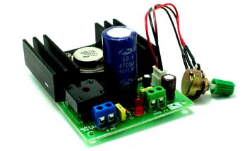
This project provides a variable output voltage ranging from 1.2 to 32 V @ 5 A. Project based on LM338K IC, LM338K is adjustable 3 terminal positive voltage regulator capable of supply in excess of 5A over a 1.2V to 32V output range, simple circuit consist few components.
Features
Input Supply : 24 VAC or 30 VDC, 5 Amp
Output : variable output from 1.2 to 32 V @ 5 A regulated low ripple DC voltage
Heatsink for regulator IC
Onboard bridge rectifier to convert AC to DC
LED indication at input of IC
Thermal overload/short circuit protection (provided by IC feature)
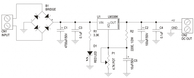
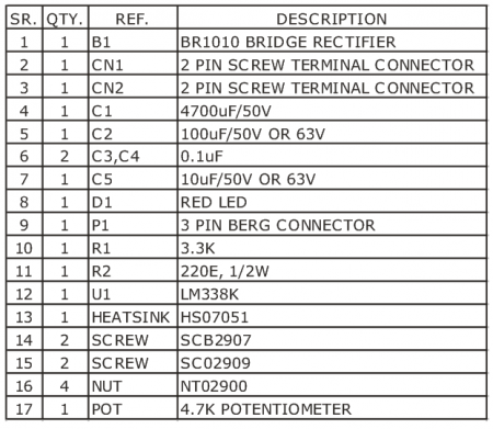
This project provides a variable output voltage ranging from 1.2 to 32 V @ 5 A. The project based on LM338K IC. LM338K is an adjustable 3 terminal positive voltage regulator capable of supplying a maximum of 5A over a 1.2V to 32V output range. The circuit is simple and consists of a few components.
Features
Input Supply : 24 VAC or 30 VDC, 5 Amp
Output : variable output from 1.2 to 32 V @ 5 A regulated low ripple DC voltage
Heatsink for regulator IC
Onboard bridge rectifier to convert AC to DC
LED indication at input of IC
Thermal overload/short circuit protection (provided by IC feature)
Screw terminal connector for easy input and output connection
Berg connector for connecting potentiometer (POT) to the PCB
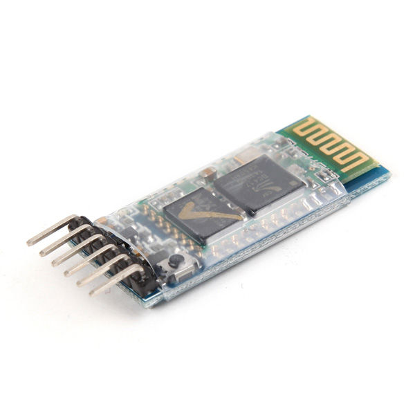
TechDepot Egypt @ instructables.com has published a tutorial on how to connect a HC-05 Bluetooth module to Arduino. Turorial shows how to connect the module with Arduino and example code is included.
It is worth noting that the HC-05 power in (Vcc) uses 5V, while the transmit and receive (TXD and RXD) logic signal uses 3.3V. Accordingly sending signals from the HC-05 module to Arduino is ok as the Arduino I/O pins can safely receive up to 5V but the issue is when Arduino tries to send the data to the HC-05 with signal level 5V, in this case it is required to use a voltage divider as we will see during the tutorial.
Connecting HC-05 Bluetooth Module to Arduino – [Link]