Isolated Circuit Digitally Indicates 120-/220-V Line Voltage

IFD2631_FO

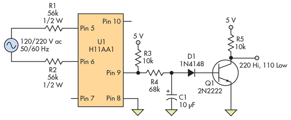
Edward K. Miguel @ electronicdesign.com has published a circuit that has output high when the votlage in input is 220V and output low when the voltage is 110V. This is often useful on motor control and power supply systems.

The circuit illustrated in the figure monitors the ac line and provides a basic output indicating whether it is at 120 V or 220 V, with the output at the transistor collector going low for 120-V and high for 220-V inputs.

Isolated Circuit Digitally Indicates 120-/220-V Line Voltage – [Link]

Dual USB Serial and I2C Converter

IMG_20160223_143440347-624x351

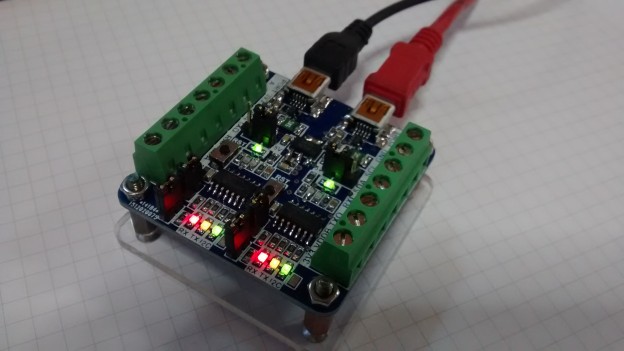
Jesus Echavarria has posted a new project, a dual USB – Serial and I2C converter to communicate with serial and I2C devices.

Hi all! After a couple of months with a lot of work, I come here again with the last board I develop before Christmas. It’s a dual USB serial and I2C converter based on two MCP2221 Microchip 2.0 USB-Serial bridges. I develop it as a need on my work with the last project I’m involved. I need to monitor a serial communication between two devices. With only one converter, I must choose between RX and TX lines to monitoring the traffic.

Dual USB Serial and I2C Converter – [Link]

DC Motor Direction Controller with tact switches

DC_Motor_Direction_Controller_IMG

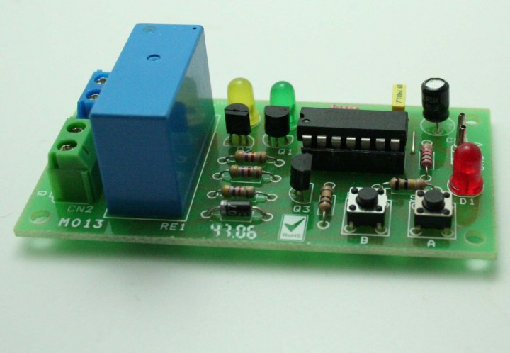
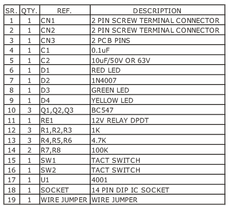
DC Motor Direction Control project offers direction control using digital logic gates and a DPDT relay.

Features

  • Supply input 12 VDC @ 75 mA
  • Power LED
  • DC Motor Direction LED Yellow/Green
  • Relay Output: up to 7 A
  • Onboard tactile switch for direction control
  • Relay based drive design with diode protection
  • LED indicator for direction indication
  • Power-On LED indicator
  • Terminal pins and screw terminal connector for easy input / output connection
  • Four mounting holes of 3.2 mm each
  • PCB dimensions 41 mm x 81 mm

DC Motor Direction Controller with tact switches – [Link]

DC Motor Direction Controller with tact switches

DC_Motor_Direction_Controller_IMG

DC Motor Direction Control project offers direction control using digital logic gates and a DPDT relay.

Features

  • Supply input 12 VDC @ 75 mA
  • Power LED
  • DC Motor Direction LED Yellow/Green
  • Relay Output: up to 7 A
  • Onboard tactile switch for direction control
  • Relay based drive design with diode protection
  • LED indicator for direction indication
  • Power-On LED indicator
  • Terminal pins and screw terminal connector for easy input / output connection
  • Four mounting holes of 3.2 mm each
  • PCB dimensions 41 mm x 81 mm

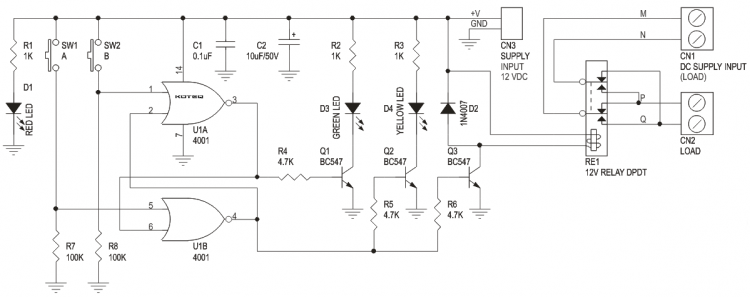
Schematic

DC_Motor_Direction_Controller_SCH


Parts List

DC_Motor_Direction_Controller_BOM

ATtiny10 Mini Breakout Board

ATtiny10-MiniBreakoutBoard

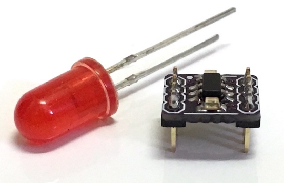
Dan Watson has designed a tiny breakout board for the Atmel ATtiny10. The board includes a bypass capacitor, a power LED and a user LED:

This breakout board is for the ATtiny10 microcontroller. The PCB is 0.25×0.325″ and uses 0.050″ header pins. The board could actually be made smaller, but I ran into the minimum PCB size limit on OSHPark. Despite the tiny size, I was able to include a 100nF bypass capacitor, power LED, and a user LED on pin PB1. That pin is also the clock pin for the programming interface, so it flashed when the board is being programmed.

ATtiny10 Mini Breakout Board – [Link]

High-band DPD Demodulator with Integrated DSA and RF Switch

The IDTF1370 is a digital pre-distortion demodulator (DPD) for power amplifiers linearization in BTS transmitter that utilize the IDT zero-distortion, and glitch-free technology that offers customers an unparalleled high-performance DPD demodulator. It utilizes the technique called pre-distortion, in digital communication it is used to improve the linearity of the transmitter performance by pre-distorting a data to counteract the distortion inherent in the power amplifier. The F1370 has an RF channel range of 1300-2900MHz, it’s IF frequency ranges 20-500MHz, a typical gain of 12.5dB, +41dBm IP3o, and a High/Low side injection. The device features an integrated DPD IC for MIMO, which eliminates the need for external IF amps, baluns, switches, and DSAs thus reduce solution cost and space significantly. It has a reduction of greater that 1-Watt power consumption compared to conventional solutions.

The device has an RF input, standby mode and attenuator setting may be set using the F1370 serial port input. It has a built-in digital step attenuator (DSA) and single-pole-double-throw switches (SP2Ts). The signal coming out of the power amplifier is receive so that the I&Q (In-phase and Quadrature) data at the Baseband can be pre-distorted before being sent to the transmitter’s digital-to-analog converter to counteract the distortion inherent in the downstream PA. The signal coupled from the PA is adjusted via a DSA to a lower level and then sub-sampled at an IF frequency of ~200 MHz which necessitates the need for a highly linear demodulator to downmix to quadrature IF from the Transmit frequency. Sampling IF_I and IF_Q independently and then digitally combining these signals can achieve an effective doubling of the sample rate. Any distortion in this path will degrade the performance of the DPD algorithm. By utilizing an ultra-linear demodulator with integrated DSA such as the IDT F1370, the ACLR and/or power consumption of the full Transmitter system can be improved significantly.

The F1370 is typically used in base station transmitter and receiver for digital pre-distortion demodulator. It is also applicable in industrial, test and measurement, broadband CATV, microwave, and wireless infrastructure and distributed antenna system.

High-band DPD Demodulator with Integrated DSA and RF Switch  – [Link]

DIY Arduino Battery Spot Welder

FSLKFRQIL2C96LD.MEDIUM

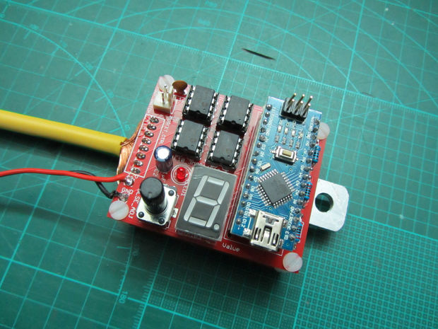
KaeptnBalu @ instructables.com has build a DIY spot welder based on Arduino board. It is powered from a 12V car battery with enough current capability to solder nickel strips on battery packs. The board generates two short pulses with the first one to be 1/8 of the time of the second one. Pulse time of second pulse is adjustable by the potentiometer and displayed on the screen in mS.

DIY Arduino Battery Spot Welder – [Link]

Raspberry Pi 3 on sale at $35

IMG_4090

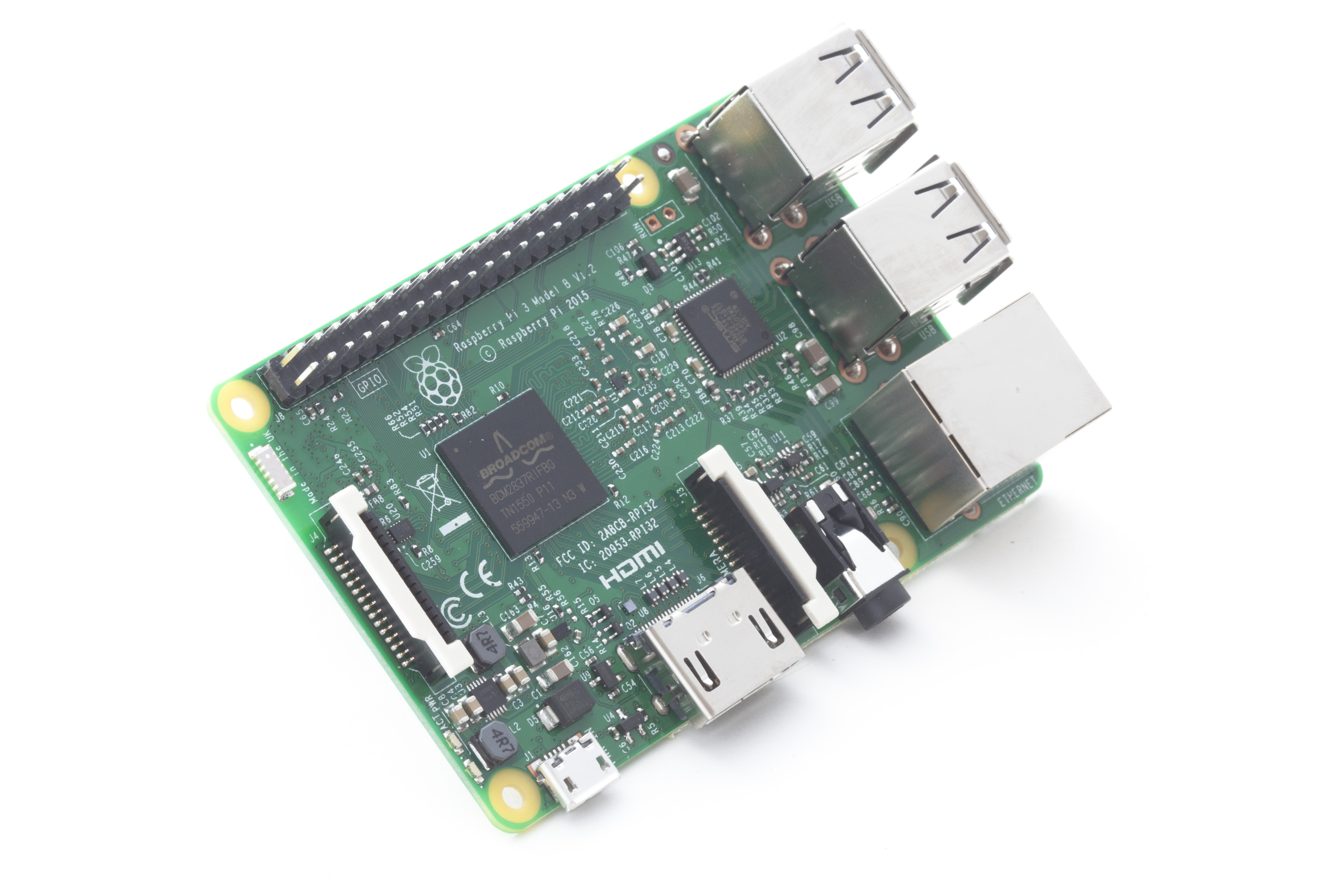
Raspberry foundation announced the Raspberry Pi 3 at the same price as the previous board. This new board features 1.2GHz 64-bit quad-core ARM Cortex-A53 CPU with ~10x the performance of Raspberry Pi 1, Integrated 802.11n wireless LAN and Bluetooth 4.1 and full compatibility with the previous boards.

For Raspberry Pi 3, Broadcom have supported us with a new SoC, BCM2837. This retains the same basic architecture as its predecessors BCM2835 and BCM2836, so all those projects and tutorials which rely on the precise details of the Raspberry Pi hardware will continue to work.

Raspberry Pi 3 on sale now at $35 – [Link]

1.2V-32V @3A Variable Switching Regulator

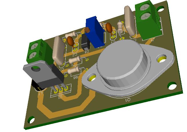
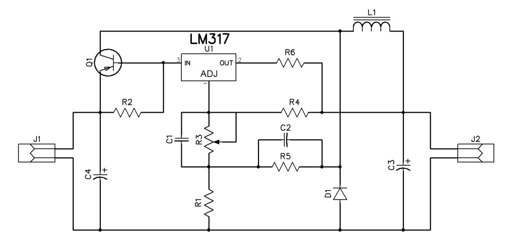
The circuit presented here is based on LM317. Generally, LM317 is known as a linear regulator IC, but here the circuit operates as a switching regulator. This circuit operates by transferring energy
from the input to the output by using a solid state switch. Power Efficiency of a switching regulator is much higher than the linear regulators. The input voltage for this circuit is 8V-35V
and it can produce the output of 1.8V to 32V, that can be varied by using potentiometer R3.

Features

  • Input(V): 8VDC to 35VDC
  • Output(V): 1.8VDC to 32VDC
  • Output load: 3A
  • PCB:68mm X 50mm

Notes

  • The real components are not same as shown in the 3D preview.

Schematic

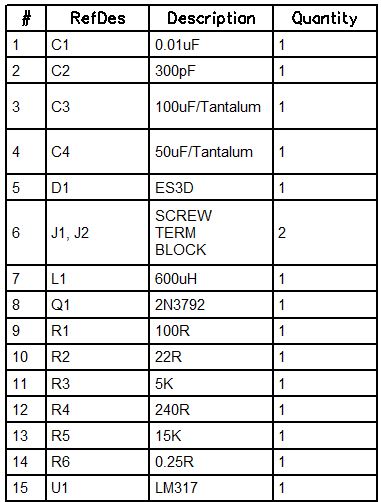
Parts List

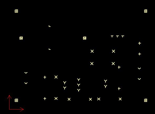
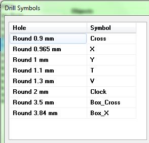
Drill Chart

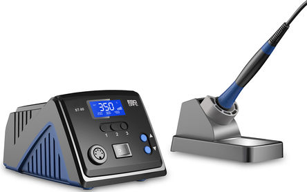
New RS Pro ST-80 Soldering Station +150°C to +480°C

R8856117-01

RS Components has launched two RS Pro solder stations with interesting features. The 60-W and 80-W solder stations have smart functions to reduce energy consumption, increase ease of use and prolong soldering tip life. The stations automatically detect if the device isn’t used for a predefined period of time and goes into standby mode or switch off if necessary. Additionally they are equipped with a LCD temperature display and a warm-up status indicator on the front panel and control is done using preset buttons or temperature adjustment buttons.

New RS Pro ST-80 Soldering Station +150°C to +480°C – [Link]

TOP PCB Companies