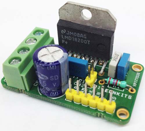
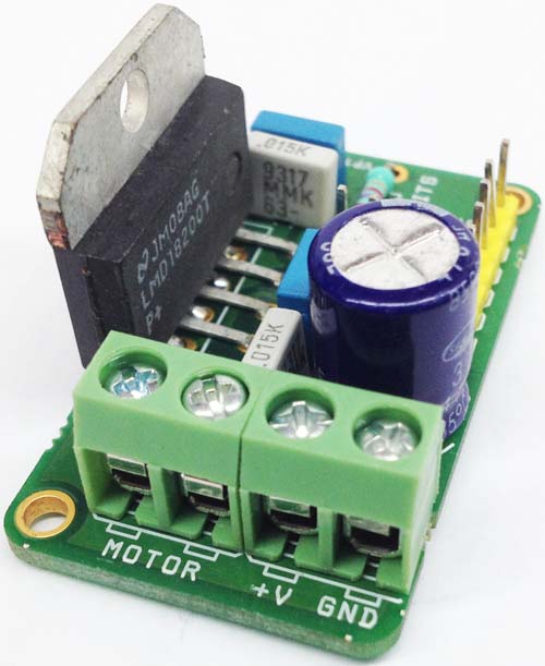
The module has been designed around LMD18200 from Texas Instruments. The LMD18200 is a 3A H-Bridge designed for motion control applications. The device is built using a multi-technology process which combines bipolar and CMOS control circuitry with DMOS power devices on the same monolithic structure. Ideal for driving DC and stepper motors; the LMD18200 accommodates peak output currents up to 6A. An innovative circuit which facilitates low-loss sensing of the output current has been implemented.
Features
- Powerful bi-directional DC Motor driver
- Screw-terminals for Power Supply and Motor Connections
- 6-pin Header connector for PWM, direction, current sense, Brake
- Delivers Up to 3A Continuous Output (6A Peak)
- Operates at Supply Voltages Up to 55V
- Low RDS (ON) Typically 0.33Ω per Switch at 3A
- TTL and CMOS Compatible Inputs
- No “Shoot-Through” Current
- Thermal Warning Flag Output at 145°C
- Thermal Shutdown (Outputs Off) at 170°C
- Internal Clamp Diodes
- Shorted Load Protection
- Internal Charge Pump with External Bootstrap Capability
- Mounting holes of 2.6 mm each
- PCB dimensions 44 mm x 25 mm
LMD18200 H-Bridge Module for DC Motor – [Link]

The module has been designed around LMD18200 from Texas Instruments. The LMD18200 is a 3A H-Bridge designed for motion control applications. The device is built using a multi-technology process which combines bipolar and CMOS control circuitry with DMOS power devices on the same monolithic structure. Ideal for driving DC and stepper motors; the LMD18200 accommodates peak output currents up to 6A. An innovative circuit which facilitates low-loss sensing of the output current has been implemented.
Features
- Powerful bi-directional DC Motor driver
- Screw-terminals for Power Supply and Motor Connections
- 6-pin Header connector for PWM, direction, current sense, Brake
- Delivers Up to 3A Continuous Output (6A Peak)
- Operates at Supply Voltages Up to 55V
- Low RDS (ON) Typically 0.33Ω per Switch at 3A
- TTL and CMOS Compatible Inputs
- No “Shoot-Through” Current
- Thermal Warning Flag Output at 145°C
- Thermal Shutdown (Outputs Off) at 170°C
- Internal Clamp Diodes
- Shorted Load Protection
- Internal Charge Pump with External Bootstrap Capability
- Mounting holes of 2.6 mm each
- PCB dimensions 44 mm x 25 mm
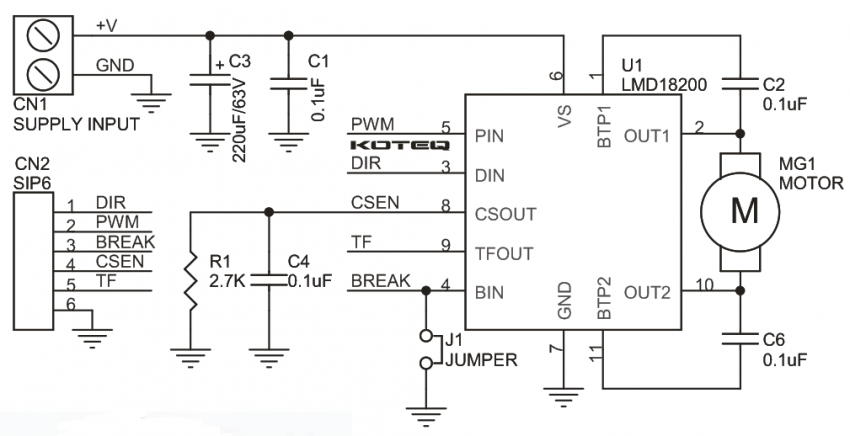
Schematic
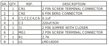
Parts List
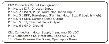
Connections
Photos


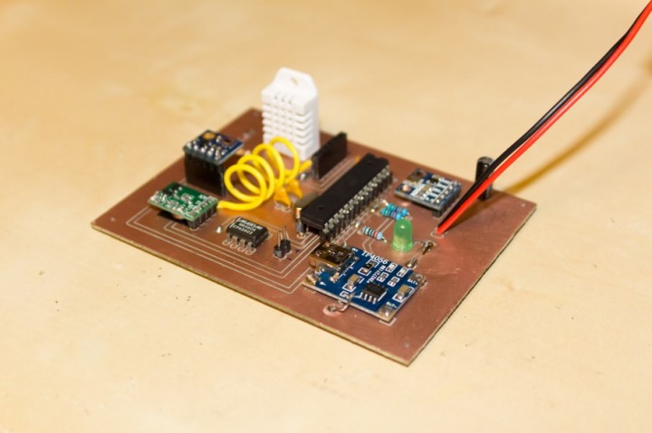
Vlad @ denialmedia.ca has build a solar powered weather station based on ATMega328 microcontroller that is able to measure temperature, a humidity, and UV radiation and it uploads measurement on WeatherUnderground network. The data are send to the air using a 433MHz link. The sensors used are DHT22, ML8511, BMP180 and a TP4056 charger IC is used to charge the Li-Po battery from a solar cell.
ATMEGA328 based Weather Station – [Link]

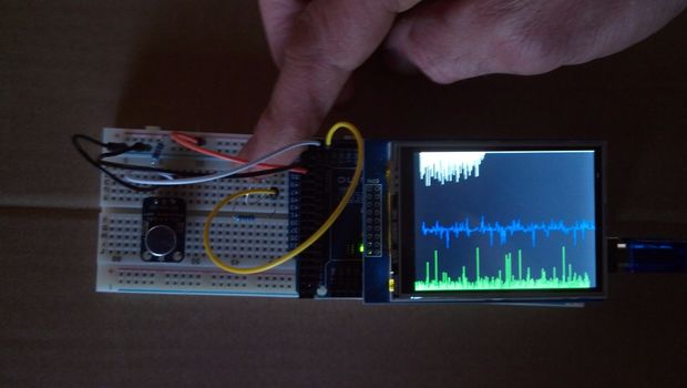
dmainmon @ instructables.com has build an analog signal graphing project using Arduino Mega 2560 and a 2.8 TFT display. This project is used to display two analog signals as line and bar graphs. Touching the screen pauses the graph and opens a menu to adjust setting for the graphs.
The project uses an Arduino Mega 2560 and UNO R3 2.8 TFT Touch Screen to display two analog signals as line and bar graphs. One signal is a photo resistor and the second is an audio sample from an Adafruit Electret Microphone Amplifier with Adjustable Gain module. The audio signal is graphically displayed twice; once in the center using a line graph and also on the bottom with a bar graph. The top graph represents the photo resistor signal.
Arduino Analog Signal Graphing on a TFT – [Link]

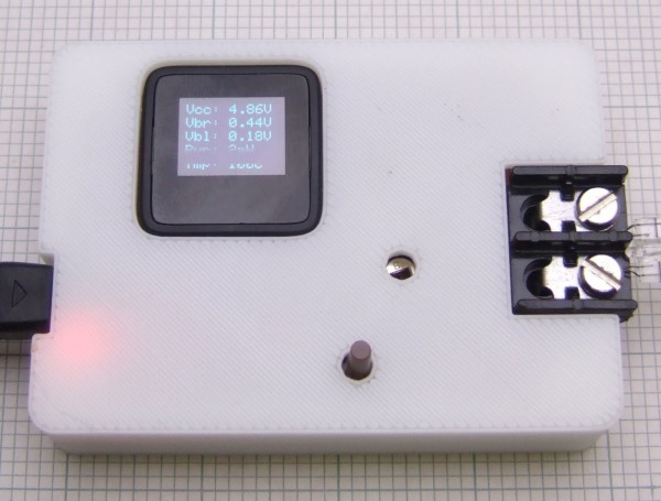
Chris Palmer has built this coolometer project to measure the cooling effectiveness of various fan:
I was wondering about how I was going to calibrate the airflow reading but then realised that the flow rate is not actually what I am interested in. It is the cooling effect the airflow has, which is what I am directly measuring. The result is simply the extra power needed to maintain a target temperature and is a measure how fast the bulb filament is being cooled. So rather than an anemometer I decided to call it a coolometer. Unfortunately Futurama used that name first. Rather than displaying megafonzies mine displays milliwatts!
Quantifying cooling system – [Link]
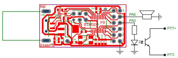
Marko Pavlin has designed a Mini USB dongle with STM32F0xx that is connected to USB and controlled via command line interface.
Mini USB dongle with STM32F0xx is suitable many for simple, mini projects. I attached speaker to Timer14 PWM output (Pin PA6) and LED (or optocoupler connected to PTT) to GPIO pin PA0
The provided software is based on USB Virtual Com Port (VCP) device. The setup is done with command line interface using terminal from any PC. The setup is stored in the internal flash and PC is not required for normal operation. The mini beacon keyer can be used when powered with 5V.
Programmable CW Morse Keyer – [Link]

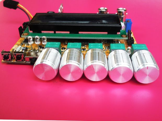
Milen @ instructables.com has designed a Function Generator based on the popular MAX038 and is controlled by ATMega328PU. Signal characteristics are displayed on a LCD screen.
The digital features of the function generator were performed by one Atmega328 chip. Its functions are the following:
controls the frequency range selection
controls the signal type (sine, rectangular, triangular, sawtooth)
measures the amplitude of the signal
measures the DC offset
measures the frequency of the signal
measures the THD of the sine signal in the audio range (this still have to be implemented)
displays all this information on a character 16×2 LCD display.
MAX038 Function generator – [Link]

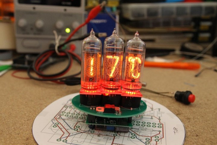
Luca Dentella has build a Nixie thermometer to measure the temperature of the liquid cooling system, file are available on Github.
I decided to log the design and the development of the project in ten blog posts. They show my “divide et impera” approach: I divided the whole project in small tasks (drive a nixie with Arduino, read the temperature from a thermistor, use an rgb led module, prepare the first prototype on a perfboard, design the pcb, assembly the final product), all described on my blog with examples and videos.
Nixie thermometer – [Link]

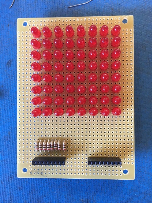
circuitspecialists.com has published a new guide on how to build your own 8×8 LED Matrix on a prototyping board. In a later guide they will show how to program it using an Arduino Compatible board.
Today we will be starting our adventure into the deeply complex, yet totally incredible world of LED Matrices. This post will be the first of an entire Arduino Matrix Programming series by Circuit Specialists.
How to build your own 8×8 led matrix – [Link]

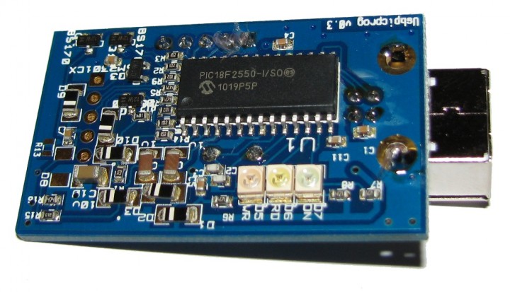
USBpicprog is an open source Microchip PIC programmer for the USB port based on PIC18F2550. PC Software, Firmware and Hardware are open source and available for free.
The hardware is built around a microchip PIC18F2550, this microcontroller has on board USB capabilities. The schematic and PCB have been designed in Kicad, an open source EDA solution
The PCB files are available in Gerber format and the schematic in pdf in the download section so that you can open them with your favourite tool.
USBpicprog – a free and open source usb pic programmer – [Link]
