
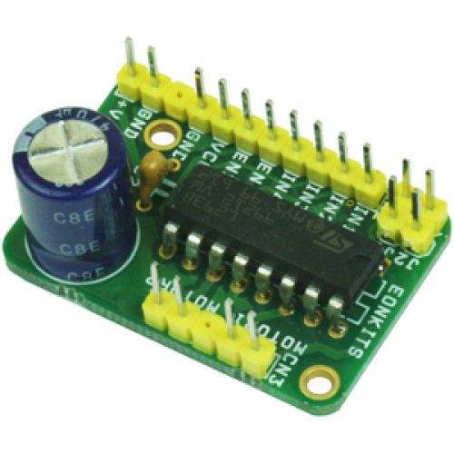
The project designed around L293D IC. The L293D device is quadruple high-current half-H driver. The 293D is designed to provide bidirectional drive current up to 600mA a voltage from 5V to 36V. L293D Adapter Board can be used as dual DC motor driver or bipolar stepper motor driver. Useful in robotics application, bidirectional DC motor controller and stepper motor driver. Separate logic supply to reduce dissipation. L293D includes the output clamping diodes for protections.
Specifications
- Motor/Logic supply 5 to 36 V
- Logic controls input 7 VDC max
- Inhibit facility/enable
- High Noise immunity
- Over temperature protection
- Capable of delivering output current up to 600 mA per channel
- The control/interface lines are accessible with Berg connector
- Header connector for motor and supply connection
- PCB dimensions 36 mm x 24 mm
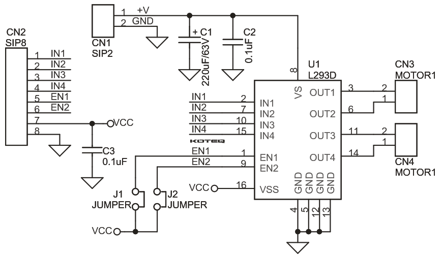
Schematic
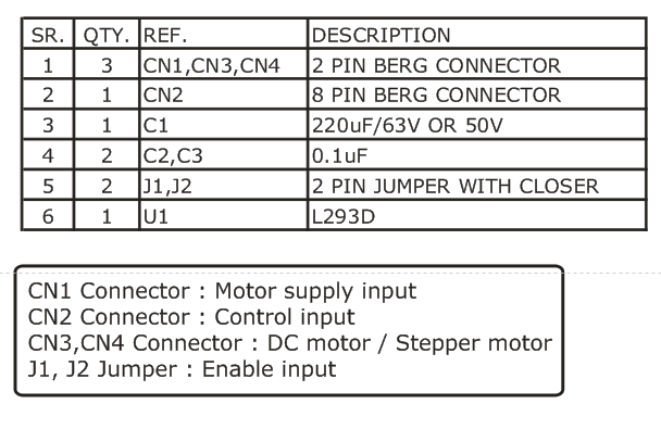
Parts List

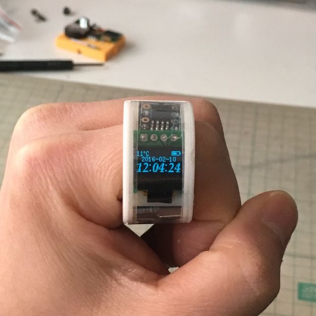
This is a great ATtiny85 watch that uses a SSD1306 OLED display and is powered by a CR1220 battery.
Today core subject, ATtiny85. Someone suggest me to use SOIC version to reduce the watch size and I found the coin cell mAh calculation method will count the battery voltage down to 2.0 V, so this watch require a low voltage version MCU to keep it stable. So I have ordered an ATTINY85V-10SU. (much expensive $_$)
ATtiny85 Ring Watch – [Link]

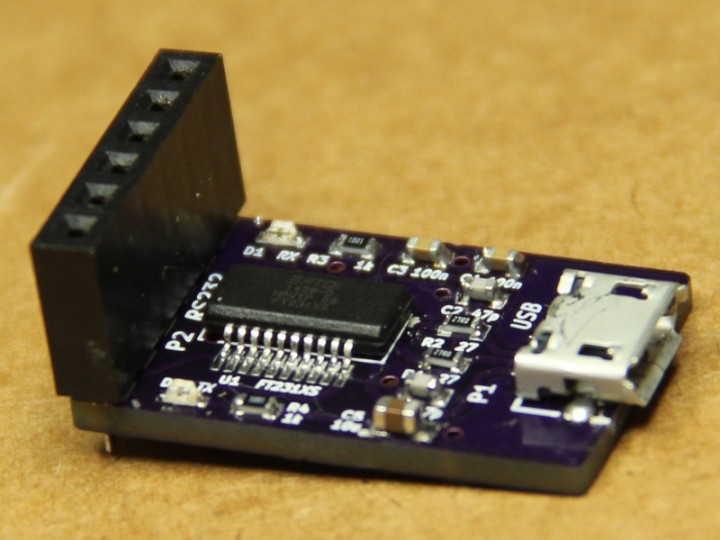
Sergey @ malinov.com has build another FTDI FT231X based USB to Serial adapter and provides the design files to the public domain.
This adapter allows connecting micro-controller boards that have 5V or 3.3V serial interfaces to a PC USB port. The converter is compatible with FTDI USB TTL Serial cables and SparkFun FTDI Basic breakout board. Compared to SparkFun board, uses much more reliable and common nowadays Micro USB connector. It is also cheaper to make (about $7 per board), and so it makes a nice project for practicing your SMD soldering skills :-).
USB to Serial Adapter using FTDI FT231X – [Link]

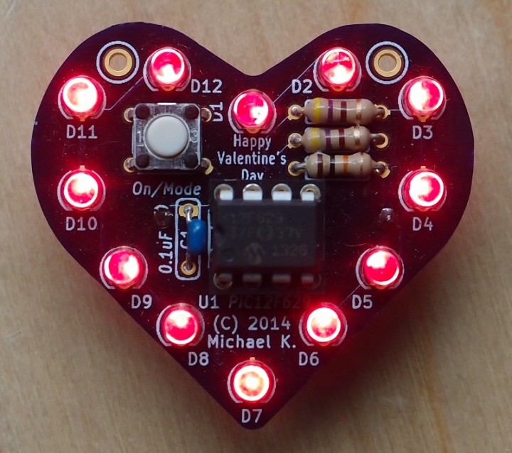
A few days before Valentine here is a great little project from Mike @ malinov.com. It’s a LED heart based on PIC12F629 that is powered using a CR2032 battery. Design files and source code are provided.
Valentine’s Heart with PIC12F629 – [Link]

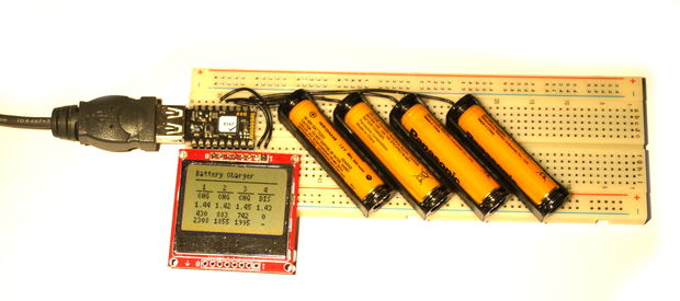
gfwilliams @ instructables.com has build a smart battery charger that is able to individually charge each battery , automatically discharge them and give you an idea of their capacity. The charger is controlled by an Espruino Pico and results are displayed on a Nokia 5110 LCD display.
If you’re anything like me you’ll end up with a lot of rechargeable batteries, none of which end up being charged properly, and some of which turn out to be completely unusable. It’d be perfect if you had a low-power battery charger that you could leave on all the time, that would charge your batteries individually, automatically discharge them, and give you an idea of their real capacity. That’s what you’ll make in this tutorial!
Smart Battery Charger – [Link]

People who are visually impaired usually use a staff to guide them as they walk. They tap with their staff to know if an obstacle is present around. Others use the echolocation technique. They produce a clicking sound through their tongue, foot, and fingers and through this they detect objects from their surrounding by sensing the echoes produced.
The design above is a simple project that aims to assist visually impaired persons by having a staff that produces a beep/click sound that they can use for echolocation and also has an ultrasonic sensor that alerts the user if there is an obstacle ahead. Inside the handle of the staff, the control circuit is located. Below it, the speaker is positioned facing front to release in a forward direction the beep/click sounds for the user to sense what is ahead. The speaker is connected to PWM pin of the microcontroller to produce sound. An ultrasonic sensor is located at the base of the staff. It is connected to an interrupt pin of the microcontroller. The continuous beep/click sound is replaced by an alarm sound when the sensor detects an obstacle. With this, additional aid is provided to the user especially to those who are not trained to be capable of echolocation. The base circuit and the control circuit in the handle are connected through the use of 179840-1 and 177900-4 Power Double Lock from TE Connectivity. These are headers and crimp housing connectors that provides durability to the design. The feature locking capability that secures the mating of the circuits connected together.
The design is operated with a +5V battery and has a switch to ON/OFF the circuit. The project is programmed to detect objects half meter and below. Beyond this range, the design will not alarm for the user to have a lesser restriction in moving. With this design, visually impaired users don’t have to tap their staff hard, which could hit someone or something.
Staff with Click Sound and Obstacle Alarm – [Link]
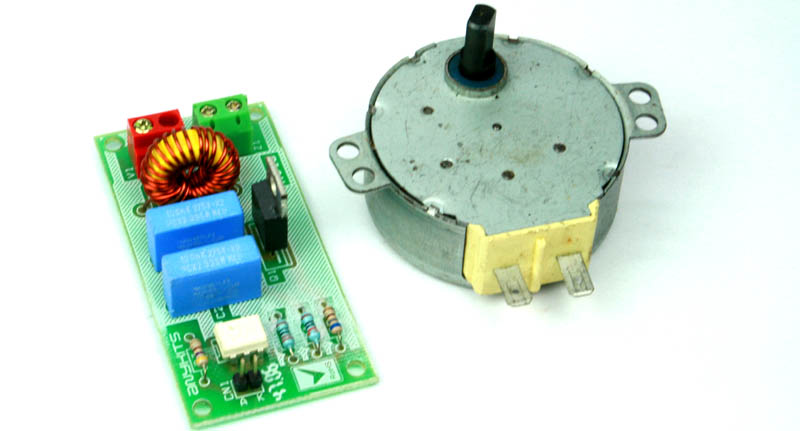
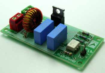
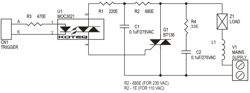
AC Solid state Relay for Inductive Load offers simple On/Off type Switch Control with TTL compatible input signal.
- Input signal : 2 ~ 5 VDC, TTL compatible
- Output : up to 500 W
- Mains supply input 230 VAC or 110 VAC
- Optically isolated Triac based design
- Power Battery Terminal (PBT) and Terminal pins for easy input / output connection
- Four mounting holes of 3.2 mm each
- PCB dimensions 35 mm x 72 mm
AC Solid state Relay for Inductive Load – [Link]
AC Solid state Relay for Inductive Load offers simple On/Off type Switch Control with TTL compatible input signal.
- Input signal : 2 ~ 5 VDC, TTL compatible
- Output : up to 500 W
- Mains supply input 230 VAC or 110 VAC
- Optically isolated Triac based design
- Power Battery Terminal (PBT) and Terminal pins for easy input / output connection
- Four mounting holes of 3.2 mm each
- PCB dimensions 35 mm x 72 mm
Schematic
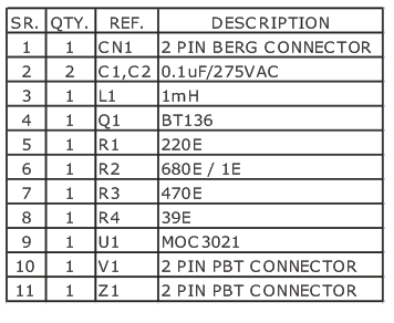
Parts List
Photo

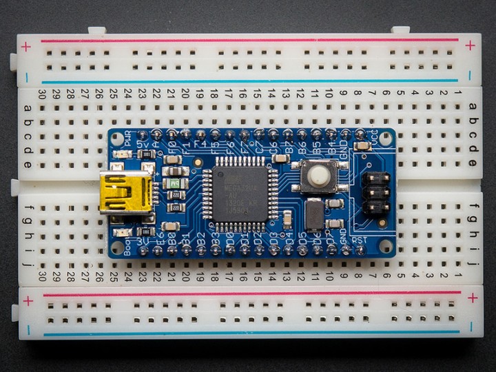
adafruit.com has published a new tutorial for their Atmega32u4 breakout board. It discuss on how to use it with AVRdude and how to setup and use it with Arduino IDE.
We like the AVR 8-bit family and were excited to see Atmel upgrade the series with a USB core. Having USB built in allows the chip to act like any USB device. For example, we can program the chip to ‘pretend’ it’s a USB joystick, or a keyboard, or a flash drive! Another nice bonus of having USB built in is that instead of having an FTDI chip or cable (like an Arduino), we can emulate the serial port directly in the chip. This costs some Flash space and RAM space but that’s the trade-off.
Atmega32u4 Breakout Board Tutorial – [Link]

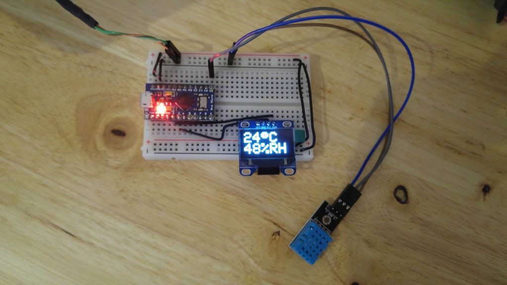
jazzycamel @ instructables.com has published an Arduino based Hydrometer with OLED display. It uses an Arduino Leonardo Pro Micro, an Adafruit SSD1306 OLED display and DHT11 digital temperature and humidity sensor.
We have been having some condensation and mould issues in our apartment recently due to, I think, the humidity levels. Our property is relatively newly built and, as such, has very good insulation properties (double glazed windows etc.).
Quick Arduino Hygrometer with OLED display – [Link]
