
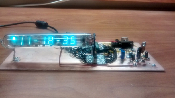
Daniel Johnson @ danielelectronics.com has build a VFD Tube Clock based on MSP430 microcontroller and explains it’s code.
I wanted to do a follow-up to my last clock build, the MSP430 Analog Gauge Clock, reusing some of the code from that project, and I had an IV-18 vacuum florescent display (VFD) tube that I bought on Ebay. Also, I wanted to finish the project before Christmas break was over. That didn’t happen. But I did manage to get the code written and most of the hardware built.
MSP430 VFD Clock – [Link]

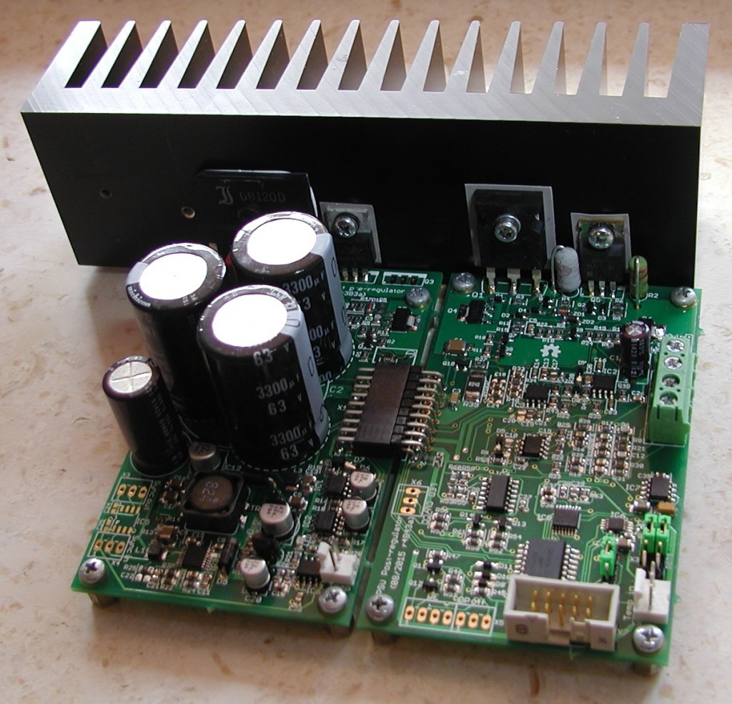
Denis @ envox.hr has designed a great PSU that is reliable, modular, programmable and of course Open source. The power supply is controlled by an Arduino and a touchscreen TFT screen is used to monitor and control it. It comes with a bunch of features you can check on the link below.
The programmable bench power supply project was an attempt to create reliable, modular, open and programmable power supply that can be used for various tasks starting with powering breadboard, charge (or to some extent discharge) batteries of various types and sizes or use as a tool in school/educational and science experiments.
Arduino Controlled Modular Bench Power Supply – [Link]

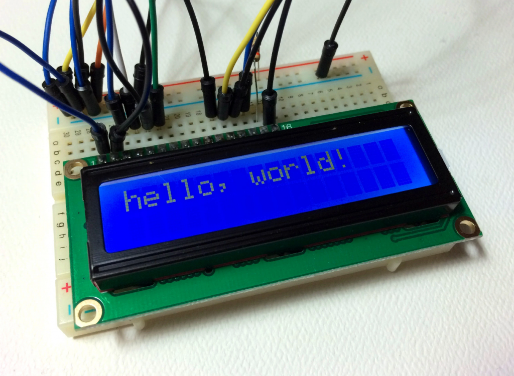
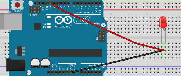
circuitbasics.com has a nice tutorial on how to use a common Hitachi HD44780 LCD display on Arduino. Many of the functions available are discussed and shown in examples.
In this tutorial, I will explain how to set up an LCD display on an Arduino, and show you (with examples) all of the functions available to program it. The display I will be using here is a 16×2 LCD display that I bought for under $10 on Amazon. They can be very useful in projects that output data, and will make your project look a lot more interesting.
How to Set Up and Program an LCD Display on an Arduino – [Link]

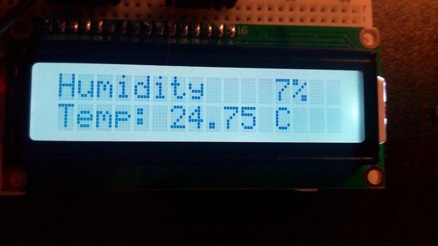
WojciechM3 @ instructables.com has build an Arduino based soil moisture sensor with character LCD, real time clock and SD card logging.
It can be very helpful with a master degree biotechnology/biology/botanics works, however remember that kind of a project can be only add as a bonus as it is in my Master thesis. Good luck with building it!
Soil Moisture Sensor with SD logging – [Link]

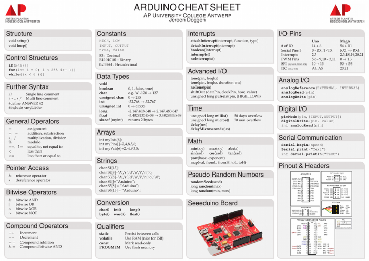
Jeroen Doggen has designed an Arduino Cheat Sheet which gives an overview of the most important Arduino commands and syntax.
Arduino Cheat Sheet – [Link]
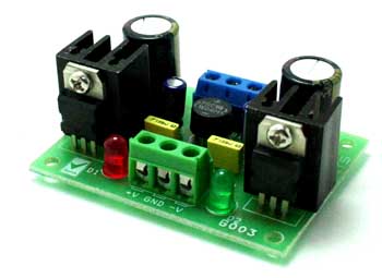
This Project provides Positive and Negative (Dual Output) 5 V @ 1 A Regulated Power Supply.
Specifications
- Input 7-0-7 VAC to 12-0-12 VAC or +/- 9 to 18 VDC
- Output : Dual output ± 5 V @ 1 A regulated low ripple DC voltage
- Heat-sink for regulator ICs
- Onboard bridge rectifier to convert AC to DC
- LED indication for both the outputs
- Thermal overload/short circuit protection (provided by IC feature)
- Screw terminal connector for easy input and output connection
- Filter capacitors for low ripple DC output
- Four mounting holes of 3.2 mm each
- PCB dimensions 46 mm x 60 mm
5V Symmetrical Regulated Power Supply – [Link]
This Project provides Positive and Negative (Dual Output) 5 V @ 1 A Regulated Power Supply.
Specifications
- Input 7-0-7 VAC to 12-0-12 VAC or +/- 9 to 18 VDC
- Output : Dual output ± 5 V @ 1 A regulated low ripple DC voltage
- Heat-sink for regulator ICs
- Onboard bridge rectifier to convert AC to DC
- LED indication for both the outputs
- Thermal overload/short circuit protection (provided by IC feature)
- Screw terminal connector for easy input and output connection
- Filter capacitors for low ripple DC output
- Four mounting holes of 3.2 mm each
- PCB dimensions 46 mm x 60 mm
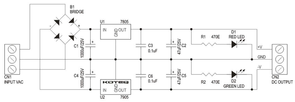
Schematic
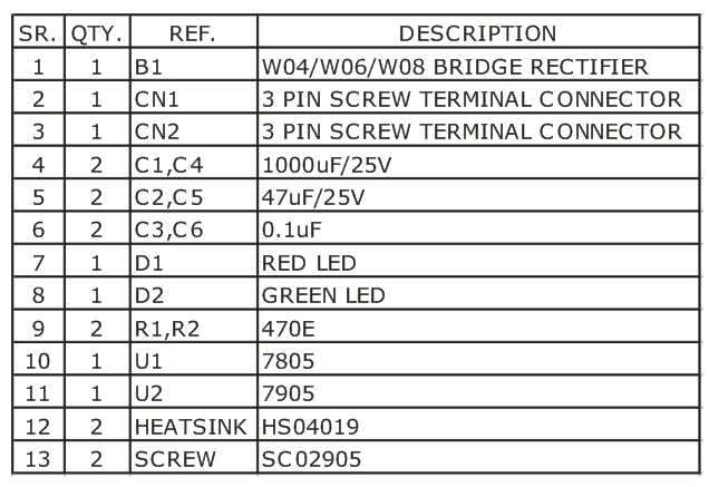
Parts List

eliesalame @ instructables.com has written an introduction course to programming Arduino. It is focused on those who just starting now in the Arduino world.
It is meant to be a beginners guide that includes detailed explanation about the basic statements and functions. Most of the sketches I use are taken from the Arduino IDE for their simplicity. I wrote this guide when I first started working with Arduino as a way to help me code easier.
Arduino 101 Fundamentals – [Link]

A WiFi (Wireless Fidelity) is a technology that uses the 2.4GHz UHF and 5GHz SHF ISM radio bands to allow devices such as computers, smartphones, digital cameras, tablet computers, etc. to network. Nowadays the WiFi technology is being used by cities to provide free or low-cost Internet access to residents. The WiFi is inexpensive and is easy to setup but it is also unobtrusive. The people may not know that they are in a hotspot unless they open their smartphones or tablets and stream movies on it.
This reference design is a simple circuit that helps WiFi users determine if there is a hotspot nearby. The circuit uses a WiFi chip, a crystal, an SPI flash and some other external components to detect if there is a WiFi network available within the area. The WiFi chip is programmed to spot wireless networks and display the result on a small light emitting diode (LED) connected to one of the GPIO pins of the WiFi chip. The LED will just keep on blinking if there is no wireless network available within the area. As soon as the WiFi chip detects a network, the LED will stop blinking and become steady.
The prototype of this circuit must be in small size so that it is wearable. The WiFi chip and the LED with the battery can be soldered into two different PCBs to make the prototype smaller. The TE Connectivity 87220-8 male and 5-534237-6 female header then connects the WiFi and the LED PCBs. The WiFi chip only consumes small power especially when it is in standby mode. But to conserve power when it is not used, the user can turn OFF the WiFi detector using the TE Connectivity MLL1200S slide switch.
Wearable WiFi Detector – [Link]
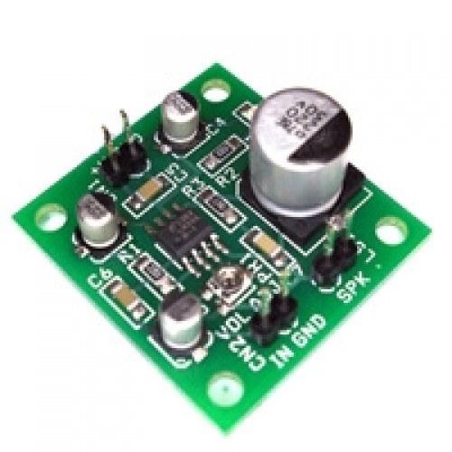
The Tiny Audio Amplifier MODULE is a good choice for battery operation. It is based on LM386 IC, useful in various applications like robotics, science projects, intercom, FM radio and many more.
Specifications
- Power Supply 6V-9V
- 300mW Output @ 8Ohms Load
- On Board Potentiometer for Audio Level Adjust
- Header Connecter for Supply, Signal in and Speaker
- On Board Power LED
- Input: Standard Audio Signal
LM386 SMD Audio Amplifier Module – [Link]
