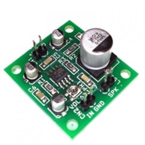
The Tiny Audio Amplifier MODULE is a good choice for battery operation. It is based on LM386 IC, useful in various applications like robotics, science projects, intercom, FM radio and many more.
Specifications
Power Supply 6V-9V
300mW Output @ 8Ohms Load
On Board Potentiometer for Audio Level Adjust
Header Connecter for Supply, Signal in and Speaker
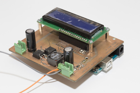
In this video we learn how to build a very usefull project. An Infrared thermometer, using the MLX90614 IR temperature sensor and the a Nokia 5110 LCD display shield. We are also using an Arduino Uno but you can use any Arduino board you like.
Arduino IR thermometer using the MLX90614 IR temperature sensor – [Link]
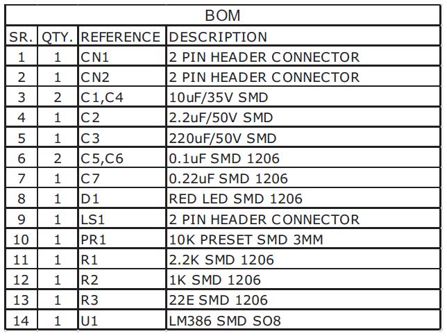
MichaelC349 @ instructables.com has designed an Arduino Mega 2560 board with bare minimum components and small size. The resulting board is bootloaded using an Arduino UNO and an external USB to serial adapter is used to program it.
Personally to be used for robotics projects that require ATmega2560’s 256 KB flash and digital/analog pins, where the size, weight, and USB port location of the original design is not ideal.
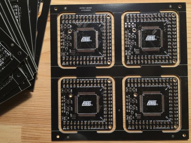
In this article Rui Santos help us solve the main issues that may arise when trying to flash a new firmware or uploading scripts on ESP8266 Wifi module. He discuss about NodeMCU flasher and how to use it successfully and also he discuss about ESPlorer IDE and it’s use.
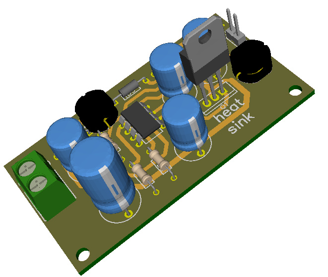
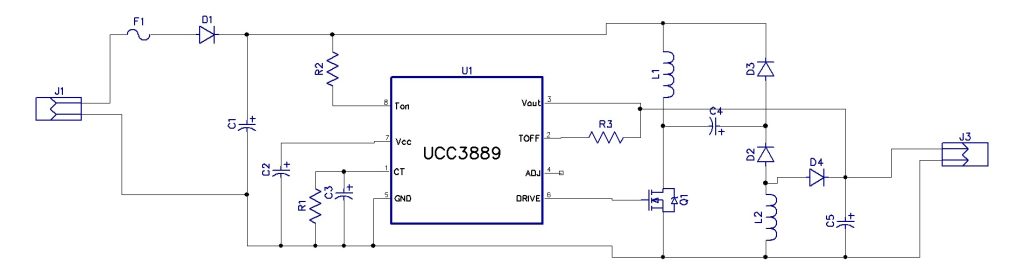
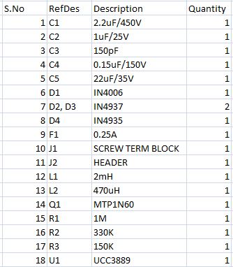
In electronics field, generating low voltage DC from AC mains (220V/110) is often necessary. Many electronic circuits work at an input voltage levels of 5V or 12V etc. For such circuits a transformer has to be used to step down the AC mains voltage to the required DC voltage level. Though using a transformer is the most familiar method, it has some dis-advantages, its expensive, it’s heavy and it has big size. The circuit presented here can supply an – non isolated from mains – output voltage of 12VDC for an input of 85-265 VAC without using a transformer.
Features:
Input (V): 85V AC to 265V AC
Output (V): 12V DC
Max Current: 80mA
PCB:70mm X 38mm
Notes:
The above circuit deals with lethal AC voltage levels. Its very dangerous to work with it, without proper experience and precautions!
Extreme caution is advised while experimenting/building this circuit as the output isn’t isolated from mains.
The components are close to what shown in the 3D preview
Lukas Fässler has designed a MPPT Solar Charger Arduino Shield and document it on the link below. A Solar MPPT charger is used to convert the solar panel voltage to the optimal voltage for charging a battery in the most efficient way. This way the solar panel works on the maximum power point and thus delivering maximum power to the battery.
The basic idea behind an MPPT solar charger is simple. A solar panel has a certain voltage (in the region of 17 to 18 volts for a 12 volts panel, somwhat dependent on temperature) at which it provides most power. So as long as the battery needs charging, you want to pull just as much current to reach this voltage. But once the battery is full you need to avoid overcharging the battery. So you want to maintain a maximum voltage for your battery (somewhere around 13.8 volts for a 12 volt lead acid battery) and no longer care about the pannel’s voltage.
David @ robotroom.com build a microcontroller based LED tester with LCD display that shows the LED voltage, the current limit in mA, the desired led voltage and the calculated resistor value. The LED tester is based on ATtiny84 mcu which performs all the measurements and calculations and updates the display. Build details on the link below.
The adjustment trimpots are on the end of the tester. The trimpot with the thumb dial is to indicate the target circuit voltage (usually 5 V or 3.3 V). The other trimpot requires a screwdriver, because it controls current, which I usually want to keep at 20 mA.
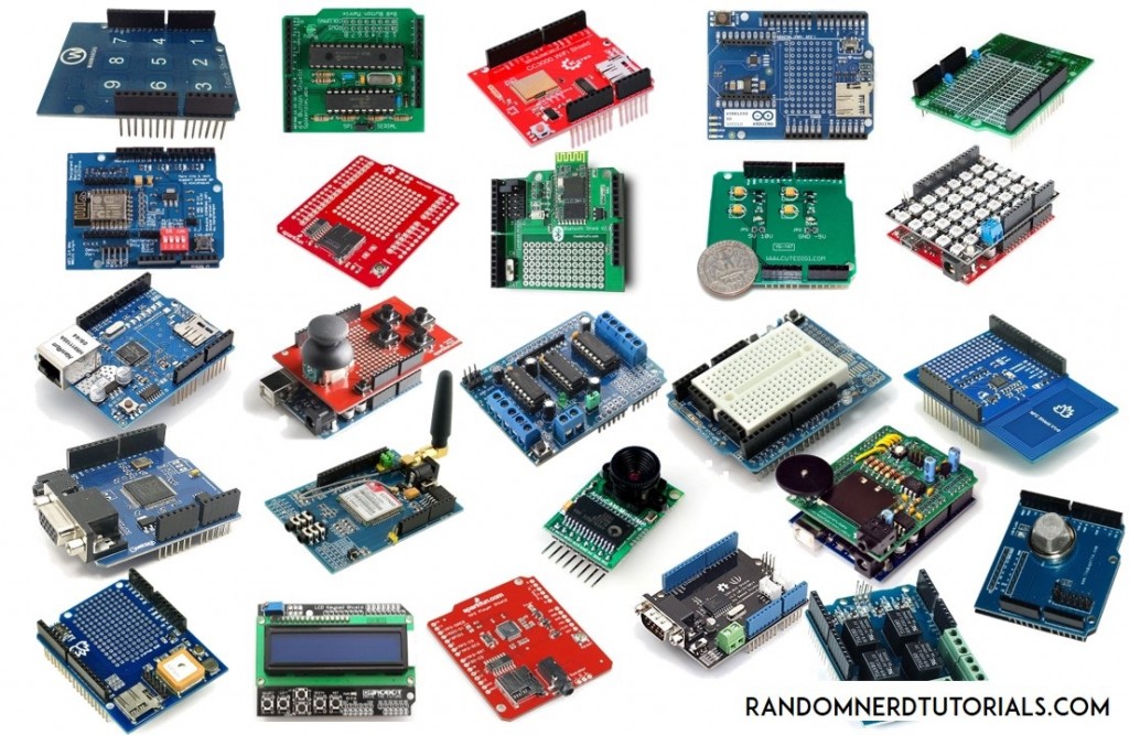
Rui Santos @ randomnerdtutorials.com has compiled a list of 25 useful Arduino Shields that you might want to use on your next projects. The list includes Ethernet shield, Relay, Motor, LCD and many more.
Arduino shields are boards that will expand the functionalities of your Arduino. You just need to plug them over the top of the Arduino board. There are countless types of shields to do countless tasks.
25 Useful Arduino Shields That You Might Need to Get – [Link]
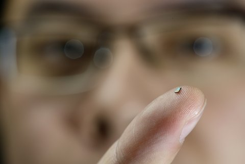
Researchers at the Eindhoven University of Technology in the Netherlands have created what they call the tiniest temperature sensor that is powered by the same wireless network it uses to communicate data. The sensor measures 2 square millimeters and needs no physical connection to send data. The current version of the sensor has a range of 2.5 centimeters but this is something to be improved in future versions.
The sensor contains an antenna that captures the energy from the router. The sensor stores that energy and, once there is enough, the sensor switches on, measures the temperature and sends a signal to the router. This signal has a slightly distinctive frequency, depending on the temperature measured. The router can deduce the temperature from this distinctive frequency.
The world’s tiniest temperature sensor is powered by radio waves – [Link]
The Minibot is a small autonomous robot vehicle that uses phototransistor that can detect lightness patterns on the ground to follow the edges of the dark lines. It has a MC9RS08KB4 MCU, coin cell, motor, and a phototransistor. The MC9RS08KB4 is part of the MC9RS08KB12 series, a family of RS08KB 8-bit microcontrollers. It features a 4KB flash size, 14 to 18 I/O pins, 8 to 12 channels of ADC, and a 126 RAM size.
The minibot is designed to be smaller than the hand and can be powered using a 3.6V coin cell. It uses a MC9RS08KB4 8-bit microcontroller. The two phototransistors are used as lightness sensors connected to the input pins of an analog comparator (PTA0 and PTA1). The two 2N7002K N-channel motors are connected to pin PTB4 and PTB5 that can be configured to the PWM ports. The LED is used for surface lighting.
The Minibot is applicable to automated guided vehicle that may be developed to larger robot or smaller robot for specific applications. The MC9RS08KB4 can be used in toys, handheld instruments, lighting control, battery charger and management, and simple logic replacements.