Maker’s rule, the feature packed PCB multi-tool

23602748930_9d9270b930_z

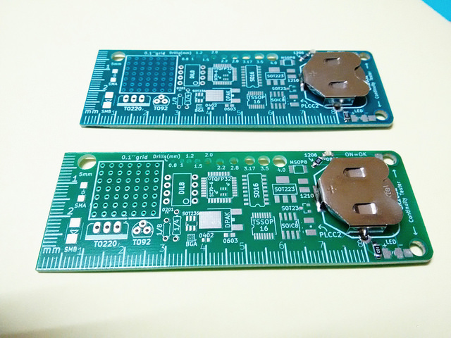
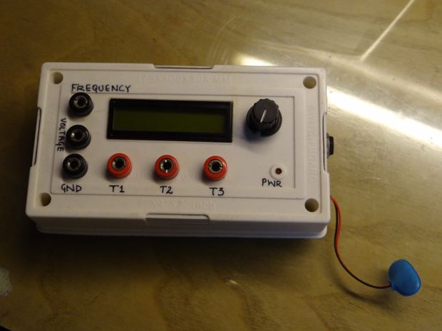
Rohit Gupta @ rohitg.in has designed a new version of his maker’s rule that is compact and packs many features like a LED tester and continuity tester:

It has been a while since i posted my Tinker Rule which i made during college days. I received a few requests for the ready to etch pdf which helped me gauge if this seemed to be useful to people. The response was somewhat positive and so, i decided to put in some extra effort and make it handy, portable and manufacturable !

Maker’s rule, the feature packed PCB multi-tool – [Link]

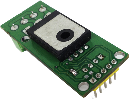
DC Output Solid State Relay

DC_Solid_State_Relay_I052A

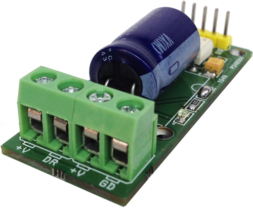
DC Output Solid State Relay 10Amps 60V DC (Optically Isolated Input)

This project has been designed around TLP250/352 which is Opto-Coupler IGBT/MOSFET Gate Driver from Toshiba and Mosfet IRFP260 from IR, This relay consists of optically isolated gate driver and low impedance Mosfet. The combination of low resistance and high load current handling capabilities make this Relay suitable for a variety of switching applications. These devices are ideally suited for controlling high voltage and current DC loads with solid state reliability while providing 3750V isolation from input to output.

A solid-state relay (SSR) is an electronic switching device that switches on or off when a small external voltage is applied across its control terminals. SSRs consist of a Opto-isolator which responds to an appropriate input (control signal), a solid-state electronic switching device which switches power to the load circuitry, and a coupling mechanism to enable the control signal to activate this switch without mechanical parts. This relay designed to switch DC Load up to 10Amps. It serves the same function as an electromechanical relay, but has no moving parts. Solid-state relays have fast switching speeds compared with electromechanical relays, and have no physical contacts to wear out. Input trigger voltage 3V to 9V DC (1.5V to 12 V with Transistor) and output load 10Amps and supply 12V to 60V DC (100V DC also Possible). Gate Driver required supply 12V to 18V DC. Heat sink required for peak load.

DC Output Solid State Relay – [Link]

DC Output Solid State Relay

DC_Solid_State_Relay_I052A

DC Output Solid State Relay 10Amps 60V DC (Optically Isolated Input)

This project has been designed around TLP250/352 which is Opto-Coupler IGBT/MOSFET Gate Driver from Toshiba and Mosfet IRFP260 from IR, This relay consists of optically isolated gate driver and low impedance Mosfet. The combination of low resistance and high load current handling capabilities make this Relay suitable for a variety of switching applications.  These devices are ideally suited for controlling high voltage and current DC loads with solid state reliability while providing 3750V isolation from input to output.

A solid-state relay (SSR) is an electronic switching device that switches on or off when a small external voltage is applied across its control terminals. SSRs consist of a Opto-isolator  which responds to an appropriate input (control signal), a solid-state electronic switching device which switches power to the load circuitry, and a coupling mechanism to enable the control signal to activate this switch without mechanical parts. This relay designed to switch DC Load up to 10Amps. It serves the same function as an electromechanical relay, but has no moving parts. Solid-state relays have fast switching speeds compared with electromechanical relays, and have no physical contacts to wear out. Input trigger voltage 3V to 9V DC (1.5V to 12 V with Transistor) and output load 10Amps and supply 12V to 60V DC (100V DC also Possible). Gate Driver required supply 12V to 18V DC. Heat sink required for peak load.

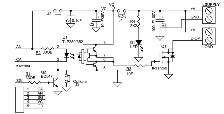
  • NOTE 1: Q2, R1, J2 Are Optional for Low Current Trigger Signal Input
  • NOTE 2: J1 (VC-J) Close In Case of Load Supply and Logic Gate Supply are same 12V to 18V DC for single supply input operation
  • NOTE 3: Done use R4, D1 LED If Load Supply is higher than 24V DC
  • NOTE 4: J3 for Cathode ground in case of single pulse input

Features

  • +V Supply 60V DC (100V DC Possible) For Load
  • VC Supply 12V – 18V DC for Opto-Coupler Gate Driver
  • J1 Jumper for Single Supply operations ( If the Load Supply is between 12V DC to 18V DC)
  • Load Current Up to 10Amps (Required large size Heat sink for High current Load)
  • Two Input Options: 1. Anode Cathode Input 2. Signal input through Transistor Base input
  • Input Trigger 3V to 9V DC-Anode and Cathode ( Alter Resistor Value for 24V DC Trigger Input )
  • Signal Input 1.5V to 12V DC at Transistor Base ( Alter Base Resister Value for Higher trigger input)
  • Isolation Voltage : 3750V ( Gate Driver)
  • Operation Input Frequency up to 50Khz ( Refer TLP352 Data Sheet for More info)

Connections

  1. Cathode 2. Anode 3. Low Current Signal in 4. VCC-12V-18V 5. GD-Ground
  2. +V & GD Load Supply 12V to 60V DC
  3. +V & DR Load ( DR-Drain: –Load & +V: + Load)

Applications

  • Motor Controls
  • Robotics
  • Medical Equipment
  • Railroad/Traffic Controls
  • Consumer Appliances
  • Industrial control
  • Solenoid Controls
  • TEC Drivers
  • High Current LED drivers
  • Low Voltage Halogen Lamp Dimmers
  • LED Light Dimmers
  • Tesla Coil Drivers
  • Induction Cook top
  • Home Appliances

Schematic

SCHEMATIC1 : PAGE1

Parts List

DC_Solid_State_Relay_BOM

Photos

DC_Solid_State_Relay_I052B

Video

TLP250/352 Datahseet

Photoplethysmography – IR Heart Rate Monitor

F4ZW3SBIJOMQ3G4.MEDIUM

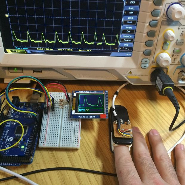
SteveQuinn @ instructables.com show us how to create a heart rate monitor using an IR phototransistor and Arduino and display the data on a TFT screen.

This Instructable documents how to create a simple heart rate monitor using Photoplethysmography with an IR phototransistor via transmissive absorption using the Arduino to process the pulsatile data and display live results via a TFT screen.

To use the source code and create the necessary circuitry you will need a reasonable grasp of electronics, knowledge of the Arduino, a DMM and some patience.

Photoplethysmography – IR Heart Rate Monitor – [Link]

Kinetis KEA128 StarterTRAK for CAN Applications

This reference design is a low-cost development kit based on Kinetis EA series MCUs that allows faster prototyping and tool reuse. This evaluation board features either one of the KEA128, KEA64 or KEA8 MCUs, depending on the board version. This particular design uses KEA128. The Kinetis EA series MCUs are a highly scalable portfolio of 32-bits ARM Cortex -M0+ MCUs aimed for general automotive applications. The family is optimized for cost-sensitive applications offering low pin-count option with very low power consumption.

This design utilizes a Kinetis KEA128 MCU, which has an ARM Cortex-M0+ core. Also, it features a CAN module, a UART module with LIN capabilities, a pulse width timer (PWT) and a keyboard interrupt module (KBI). All these peripherals along with standard serial communication protocols such as I2C and SPI offer flexibility for a wide variety of applications. The TRK-KEA board includes an onboard OpenSDA programmer and debugger, LIN physical transceiver, CAN physical transceiver, a light sensor, four LEDs and two pushbuttons for user interface.

With 2.7V-5.5V supply and focus on exceptional electromagnetic compatibility (EMC) and ESD robustness, Kinetis EA series MCUs devices are well suited to a wide range of applications ranging from body applications, powertrain companion chips or generic sensor nodes, park assistance, pump/fan controller, and motorcycle CDI/EFI. In automotive body applications, the Kinetis EA series MCUs are a great option for entry level body controller or gateway module, window/roof/sun-roof controller, immobilizer or seat/mirror controller, ambient lighting, just to mention a few.

Kinetis KEA128 StarterTRAK for CAN Applications – [Link]

ATMEGA328 Component Tester

FAD5FSEIJORXCZM.MEDIUM

baweja_akshay @ instructables.com has build a ATMEGA328 component tester that is able to test Resistors, Capacitors, Inductors, BJT, FET, Thyristors and more.

Coming upon COMPONENT TESTER so it can test almost everything, obviously not the power components because they require more current and power which our AVR Microcontroller couldn’t handle !! Oh yeah, I forgot to tell you guys that we would be using an ATMEGA328 for our build !!

ATMEGA328 Component Tester – [Link]

Building a low cost wifi camera

IMG_3759

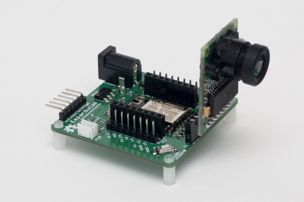
Johan @ johan.kanflo.com build his own Wifi webcam combining an Arducam Mini and a ESP8266 Wifi module. The result is the Esparducam board!

Sometime ago I came across the Arducam Mini which is quite a nice camera module from UCTronics. It is a small PCB with a two megapixel OmniVision OV2640 sensor, an interchangeable lens and an FPGA to do the heavy lifting of image processing and JPEG encoding.

Building a low cost wifi camera – [Link]

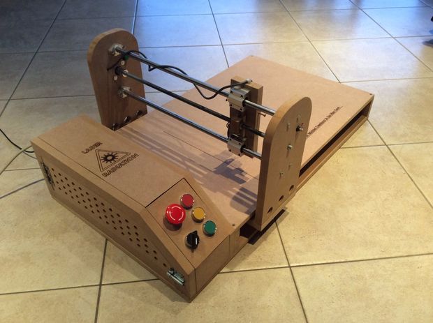
Arduino-Powered Laser Engraver

FDVTYPCIJIX6S6T.MEDIUM

MichielD99, a 16 year old Belgian teenage maker build this amazing laser engraver using Arduino UNO, two NEMA-17 stepper motors and stepper motor drivers.

This laser engraver uses a 1.8W 445nm laser module, of course, this is nothing compared to the industrial laser cutters who use lasers of (a lot) more than 50W. But this laser will do well for us. It can cut through paper and cardboard and it can engrave all kinds of wood. I haven’t tested other materials yet, but I’m sure it can engrave many other materials. l will let you know! It has a large engraving surface of about 500x380mm.

Arduino-Powered Laser Engraver – [Link]

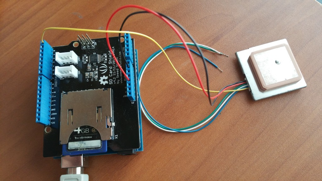
Simple Arduino SD-Card GPS/NMEA Datalogger

20160122_134926-1024x576

KF5OBS @ jaunty-electronics.com shows us how to build a minimalistic GPS datalogger. The GPS logger is based on the Arduino platform and stores raw NMEA sentences from pretty much any GPS module to a SD card.

For a project I needed to log GPS information. I had various GPS modules and plenty of Arduinos laying around the lab. At first I intended for the Arduino to capture data from the GPS module, process it and then store it onto a SD card. However, I discarded that idea in favor of more flexibility and now use the arduino merely as pass-thru device for the raw GPS data.

Simple Arduino SD-Card GPS/NMEA Datalogger – [Link]

TOP PCB Companies