OSHChip – general purpose processor board in DIP format

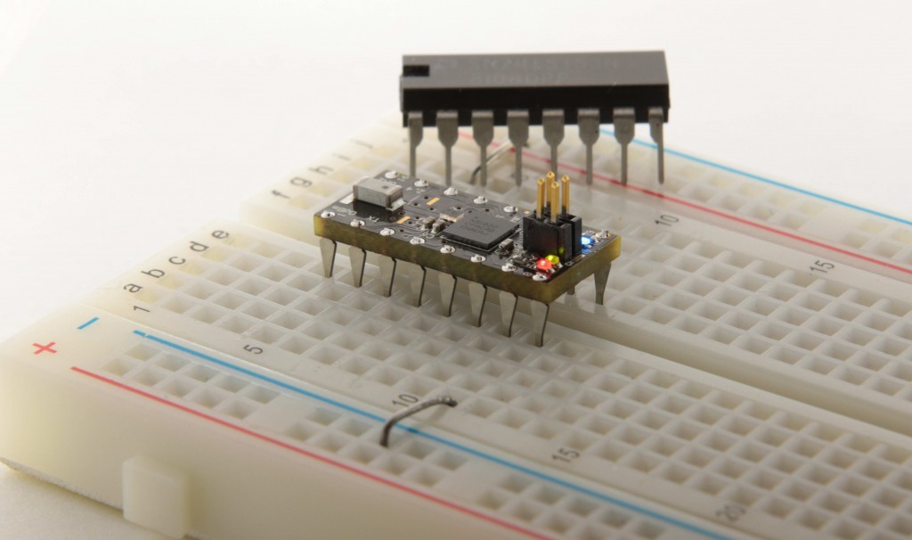
OSHChip_Black_on_breadboard

OSHChip is a general purpose processor board based on ARM Cortex-M0 32 bit processor running at 16 MHz. It includes 2.4 GHz Bluetooth Low Energy radio and a broad range of built-in Peripherals. It features 256 KBytes of Flash memory for program and data and 32 KBytes of SRAM. All this functionality comes in a tiny DIP like package which is compatible with a breadboard thus making prototyping an easy task. OSHChip is an open source project and all design files are available on github: https://github.com/OSHChip/OSHChip_V1.0_Docs

OSHChip – general purpose processor board in DIP format – [Link]

VL53L0 – Ultra-fast distance sensor

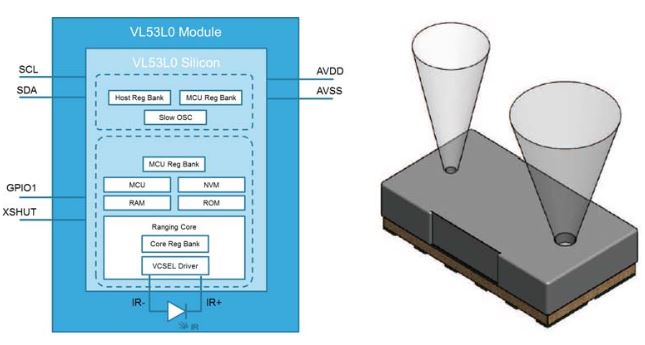
20160111120517_vl53l0

by Harry Baggen @ elektormagazine.com

STMicroelectronics has launched their second-generation distance senor VL53L0, which is based on STM’s popular FlightSense technology. This sensor is suitable for use in smartphones and tablets to make quick distance measurements for an integrated camera, but it can also be used in robots, drones and wearables.

Despite its compact dimension of 4.4 x 2.2 x 1 mm, the VL53L0 integrates a vertical cavity surface-emitting laser (VCSEL) operating at a wavelength of 940 nm, a single-photon avalanche diode (SPAD) light detector, and a microcontroller that controls the entire measurement process and calculates the measured distance. Using a 940 nm laser in combination with integrated infrared filters makes the detector insensitive to ambient light, and the laser light is not visible to the human eye.

VL53L0 – Ultra-fast distance sensor – [Link]

10 steps to selecting a microcontroller

jb20130407a

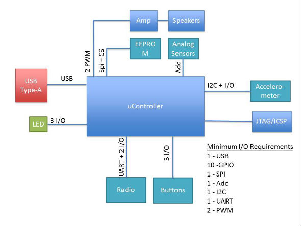
Jacob Beningo @ edn.com discuss on how to select the right mcu for your next project based on hardware and software architecture.

Selecting the right microcontroller for a product can be a daunting task. Not only are there a number of technical features to consider, there are also business case issues such as cost and lead-times that can cripple a project. At the start of a project there is a great temptation to jump in and start selecting a microcontroller before the details of the system has been hashed out. This is of course a bad idea.

10 steps to selecting a microcontroller – [Link]

Unipolar Stepper Motor Driver Circuit

This unipolar stepper motor driver circuit is used to drive a 12V unipolar stepper motor with a current rating of 1.25A. It uses PCA9537 IC, which is a 10-pin CMOS device that provides 4 bits of General Purpose I/O (GPIO) expansion with interrupt and reset for I2C-bus/SMBus applications. It consists of a 4-bit configuration register (input or output selection), 4-bit input port register, 4-bit output port register and a 4-bit polarity inversion register (active HIGH or active LOW operation). In addition, the device uses PCA9665 IC that serves as an interface between most standard parallel-bus microcontrollers/microprocessors and the serial I2C-bus allowing the parallel bus system to communicate bidirectionally with the I2C-bus.

The PCA9537 totem pole GPIO used in this circuit has a fixed I2C-bus slave address, 92H. The host controller’s firmware generates the I2C byte sequences needed to toggle the outputs and provide the waveforms at the gate inputs G1 to G4. The type of waveform will be one corresponding to wave, two-phase or half-step drive that is chosen by the user. The duration of the pulses is controlled by time delay implemented in the host controller firmware. It is shown as a reference for the various waveforms. The maximum I2C-bus speed supported by PCA9537 is 400kHz.

Motor drivers have various applications that are used when accurate positioning is required. Such applications are for use in holding or positioning, like packaging machinery, and positioning of valve pilot stages for fluid control systems. The device enhances the performance of machines and other simple devices that may significantly support industries, and other commercial entities to make the work easier.

Unipolar Stepper Motor Driver Circuit – [Link]

Using a $2 DS3231 RTC & AT24C32 EEprom from eBay

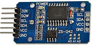
cheaprtc

Edward Mallon @ edwardmallon.wordpress.com gives us a detailed explanation about cheap RTC modules found on ebay and other places.

I built the first few beta units with the DS3231 Chronodot from Macetech (about $18 each), but I kept on stumbling across cheap RTC modules on eBay, Amazon, etc. and I eventually bought a couple to try them out. While I waited for them to ship on the proverbial slow boat, I did some digging, because these modules were (almost) selling for less than the chip itself if I bought them directly from trusted sources like Digikey, Mouser, etc.

Using a $2 DS3231 RTC & AT24C32 EEprom from eBay – [Link]

Advanced Datalogger with ATMEGA328, BMP180, DHT22, BH1750 and sd card

educ8s.tv has published another great Arduino project. It’s a ATMega328 based datalogger able to record temperature, humidity, barometric pressure and light to a SD card.

In this video we build an Advanced Data Logger with Arduino. We use a DHT22 temperature and Humidity Sensor, a Bmp180 barometric pressure sensor and a BH1750 light sensor. The project store the data in a micro SD card and can run on batteries for around 2 weeks.

Six months ago, I built my first data logger using an Arduino Nano and the DS3231 Real Time Clock. I wanted to build an advanced version of it for a long time and when I posted that idea on the website along with many other project ideas, most of the visitors voted to build this project first, so here it is! The Advanced Arduino Data logger is capable of logging, temperature, humidity, barometric pressure and light intensity for about 2 weeks using simple AA batteries. It stores the data on a Micro SD card in a .csv file format in order to be able to import this file to any data processing software afterwards.

Advanced Datalogger with ATMEGA328, BMP180, DHT22, BH1750 and sd card – [Link]

Home Thermostat With Arduino and LCD

FIQU2EUIJG49TD7.MEDIUM

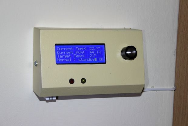
ArisK3 @ instructables.com decided to replace his home thermostat with a DIY one so he build an Arduino based thermostat with big character LCD.

Replacing a standard thermostat (SIEMENS-RAA30 16GR) with a self made, arduino-based, big LCD screen is a fun project.

Home Thermostat With Arduino and LCD – [Link]

Arduino Voltmeter Prototype

FPE52T0IJHFDMVV.MEDIUM

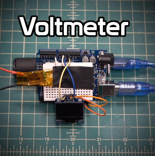
Proto G @ instructables.com has build an Arduino based digital voltmeter that is able to measure up to 30V and it’s using an OLED LCD display.

In this instructable, I’ll show you how to make a simple arduino voltmeter. It can measure voltages in excess of 30VDC depending on how you configure it. The smaller the voltage range you want to measure, the more accurate that your meter will be. This project is going to be apart of a gauss meter that I am making to measure magnetic fields strength as well as magnetic field polarity

Arduino Voltmeter Prototype – [Link]

Portable Ultrasonic Range Meter

FJPZU06IJEKJIN4.LARGE

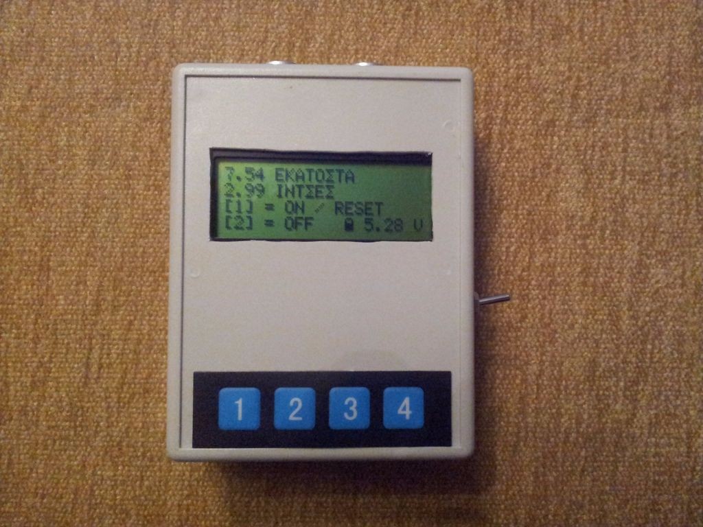
ManosM @ instructables.com has build a portable ultrasonic range meter based on ATMega328 mcu and LCD display.

This device is a small, portable ultrasonic range meter using an ATMega328 microcontroller, an ultrasonic module and a 4×20 LCD for ranging distances in meters and inches.

Portable Ultrasonic Range Meter – [Link]

AC Solid State Relay

Solid_State_Relay_IMG2

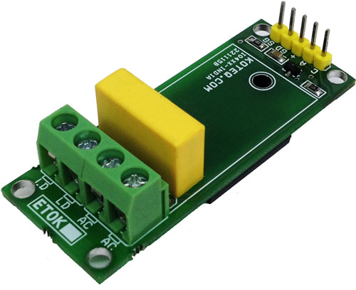
This simple circuit designed around Solid State Relay S216S02 from SHARP. The S216S02 solid State Relay (SSR) is an integration of an infrared emitting diode (IRED), a Phototraic Detector and a main output Traic. These devices are ideally suited for controlling high voltage AC loads with solid state reliability while providing 4KV isolation from input to output.

A solid-state relay (SSR) is an electronic switching device that switches on or off when a small external voltage is applied across its control terminals. SSRs consist of a opto-isolator which responds to an appropriate input (control signal), a solid-state electronic switching device which switches power to the load circuitry, and a coupling mechanism to enable the control signal to activate this switch without mechanical parts. This relay designed to switch either AC load up-to 1KW. It serves the same function as an electromechanical relay, but has no moving parts. Solid-state relays have fast switching speeds compared with electromechanical relays, and have no physical contacts to wear out.

AC Solid State Relay – [Link]

TOP PCB Companies