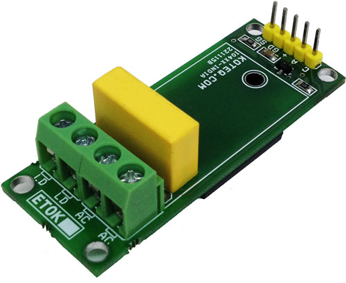
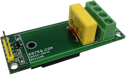
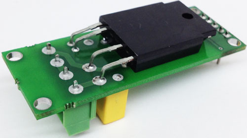
This simple circuit designed around Solid State Relay S216S02 from SHARP. The S216S02 solid State Relay (SSR) is an integration of an infrared emitting diode (IRED), a Phototraic Detector and a main output Traic. These devices are ideally suited for controlling high voltage AC loads with solid state reliability while providing 4KV isolation from input to output.
A solid-state relay (SSR) is an electronic switching device that switches on or off when a small external voltage is applied across its control terminals. SSRs consist of a opto-isolator which responds to an appropriate input (control signal), a solid-state electronic switching device which switches power to the load circuitry, and a coupling mechanism to enable the control signal to activate this switch without mechanical parts. This relay designed to switch either AC load up-to 1KW. It serves the same function as an electromechanical relay, but has no moving parts. Solid-state relays have fast switching speeds compared with electromechanical relays, and have no physical contacts to wear out.
Features
AC Load Upto 16Amps Peak
Maximum Supply input 600V AC
TTL Input Trigger Voltage across Anode and Cathode 3 to 6V @ 20mA
Input Trigger Voltage across Transistor Base 1.5V to 24V DC 5mA
Small PCB with on Board Snubber Circuit for inductive Load
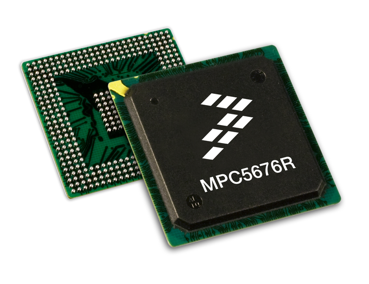
Maurizio Di Paolo Emilio has pointed us to this latest article on why to choose Freescale mcu versus Microchip ones:
The task of choosing the best micro for an application is not made easier by the multitude of suppliers you have at hand today, this being the drawback of having so many options. The main competitors on the microcontroller market are Freescale, Microchip, Infineon, STMicroelectronics, Texas Instruments, Analog Devices and Maxim Integrated Products. Comparing all of them is done by specialized and dedicated divisions within these companies or within marketing companies. We will only concentrate in this article to prove the superiority of the Freescale solutions over the ones coming from Microchip.
How to migrate from Microchip to Freescale and Why – [Link]
sameer @ sgprojects.co.in has build a LPG gas detection circuit based on LM358:
LPG gas detection project’s main idea is to implement the security system for detecting leakage of liquid petroleum gas in closed environment. In this project gas leakage is identified by using MQ6 gas sensor. A simple circuit with an Op-Amp IC is powered by a step down transformer and finally the alarm produces on detecting gas.
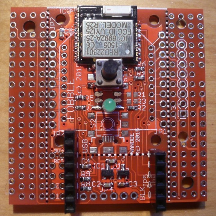
Ken Boak has designed a compact board with RFduino Bluetooth Low Energy Module:
This week I have been working on another of my standard footprint 50mm x 50mm boards – it is a general purpose wireless module carrier board:- Fobble. That’s a BLE Fob – for anyone who misses the pun.
In the last few weeks there have been a number of applications arise – that could easily be addressed with an easy to use, generic wireless platform. These have included keyfob or pendant applications – requiring a small coin cell powered board – to a generic wireless board that can be stacked to one of the processor boards to provide wireless connectivity.
Fobble – A general purpose Wireless Breakout Board! – [Link]
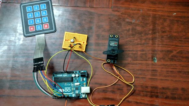
EswarD2 @ instructables.com has build an Arduino based door lock using Arduino UNO, a keypad and a servo motor.
This a door lock built as fun project.It is quite easy to build and a fun way to learn and improve your knowledge of arduino.I tried to add a 16*2 display but there werent enough GPIO pins on arduino Uno.If You are interested in adding a display you would need an arduino Mega.
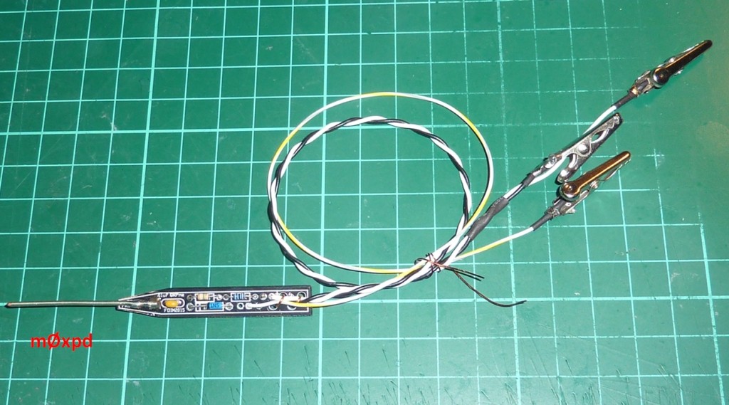
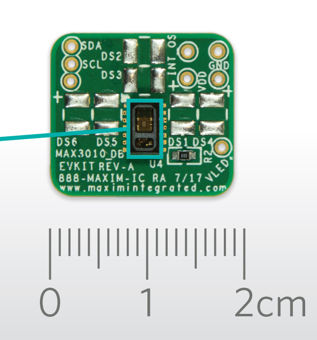
The MAX30102 pulse oximeter and heart rate integrated sensor module is claimed as the lowest power solution on the market today
The MAX30102 is an integrated pulse oximetry and heart-rate monitor module. It includes internal LEDs, photodetectors, optical elements, and low-noise electronics with ambient light rejection. The MAX30102 provides a complete system solution to ease the design-in process for mobile and wearable devices.
The MAX30102 operates on a single 1.8V power supply and a separate 5.0V power supply for the internal LEDs. Communication is through a standard I²C-compatible interface. The module can be shut down through software with zero standby current, allowing the power rails to remain powered at all times.
MAX30102 – High-Sensitivity Pulse Oximeter and Heart-Rate Sensor – [Link]
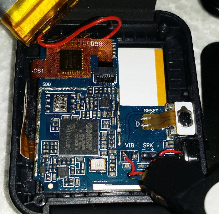
sodnpoo.com has reverse engineered a cheap smartwatch he found on amazon:
I noticed this smart watch on Amazon for the bargain price of £7.51, which was just too cheap to ignore – I didn’t expect much but I was quite surprised at how functional it actually was… Anyhow, it was never expected to stay in once piece for long, and after an hour I took the screwdriver to it.
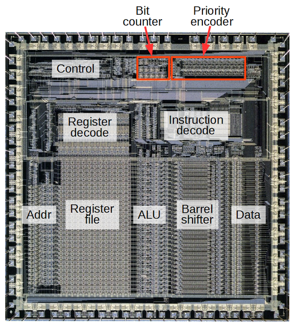
righto.com has reverse enginnered one of the most popular proccessors:
How can you count bits in hardware? In this article, I reverse-engineer the circuit used by the ARM1 processor to count the number of set bits in a 16-bit field, showing how individual transistors form multiplexers, which are combined into adders, and finally form the bit counter. The ARM1 is the ancestor of the processor in most cell phones, so you may have a descendent of this circuit in your pocket.
Reverse engineering the silicon in the ARM1 processor – [Link]
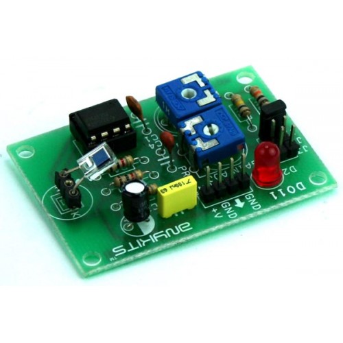
LUX Meter project has been design to measure the illumination. Illumination is luminous flux falling on surface area of photo diode. This illumination converted to corresponding voltage using Op-Amp circuit.
Specifications
Supply 9 VDC PP3 Battery @ 20 mA
Onboard Photo Diode
Onboard preset for calibration
Range selection via jumper 10mV/LUX, 1mV/LUX, 0.1mV/LUX