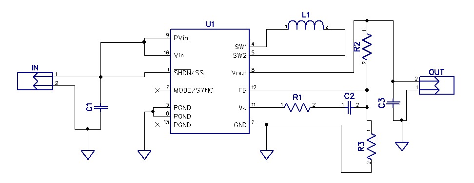
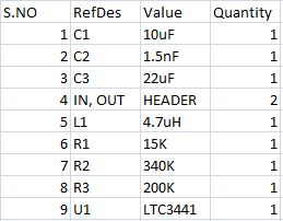
This circuit can produce an output of 3.3V and 1A current continuously for a voltage input varying from 2.5V to 4.2V. The LTC3441 is a high efficient buck boost converter which plays a vital role in portable instrumentation because of its fixed frequency operation. This circuit produces the output from a single Li-ion battery. Multiple cells can also be used within the specified range of input voltage.
2 Digit Count Down Timer is a utility Count Down timer project for upto 99 seconds of countdown time. This project can find many uses in your shack and home. The relay output remains on during the Count Down period, allowing you to interface load or alarm that you want to keep it on for a certain amount of time (in seconds).
Specifications
Microcontroller based design for greater accuracy and control
Power supply input 12 VDC 200 mA
Two 0.5″ display segments to display time
12V SPDT (Single Pole Double Throw) relay for alarm use
Single key start and dual key alarm time set function
Power and Relay-On LED indicator
Terminal connectors for connecting power supply input and relay output to the PCB
Onboard regulator for regulated supply to the kit
Crystal resonator based design for better accuracy
PCB dimensions 72 mm x 81 mm
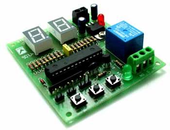
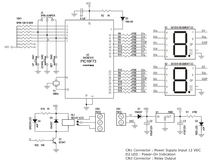
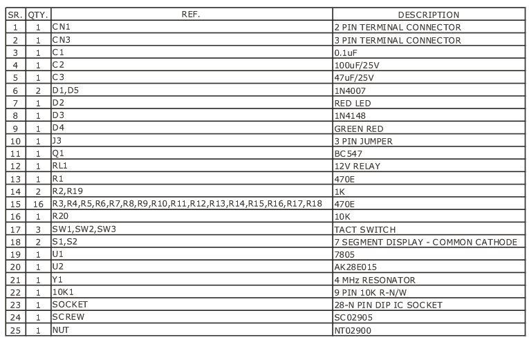
This is a microcontroller based 2 Digit (99 Seconds) Count Down Timer. This Count Down Timer is very easy to use and easy to configure. This project can find a lot of application areas where you need a device to remain ON (or OFF) for a certain period of time (upto 99 Seconds). Power to the circuit is applied at CN1 (12 VDC). D1 provides the reverse polarity protection to this kit. LED D2 confirms DC Power Supply to the board. S1 and S2 displays Count Down time. J3 provide an easy way of connecting external switches to this board. LED D4 confirms the relay status.
Operating Instructions:
The setting up of countdown period and START Function for this kit is accomplished with the help of 3 tactile switches shown as SW1, SW2 and SW3 in the schematic and labeled as UP, DOWN and SET on the PCB respectively.
Setting Time : The default value is shown on display S1 and S2 respectively. You can change this value by simply pressing the UP and DOWN key.
Start : You can start the Count Down by pressing SET key. When the Count Down starts the relay is energized, indicated with the glow of LED D4. Once the Display (S1 and S2) reaches 0 the relay is de energized.
Matthew Filipek from Cornell Univercity has build a nice smart watch with 1.7 inch touch screen, SD card, Bluetooth module and various apps.
One of the main inspirations for this project was Jared Sanson’s implementation of a DIY smartwatch (REF 0). With several design iterations, he was able to produce a watch in a very small package that can communicate with a PC via USB HID, features an OLED display, and has support for an accelerometer. As my project was to be completed in the span of a mere month, several of the components I got were purchased for their ease of use rather than their compactness.
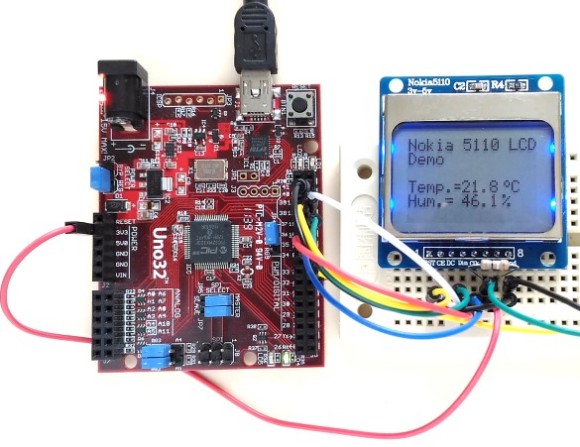
Raj @ embedded-lab.com has posted another great tutorial on how to interface a Nokia 5110 LCD to chipKIT board.
Today, we will see how to connect a NOKIA 5110 graphical LCD (used in Nokia 5110 cell phones), which is a 84×48 pixel monochrome display of about 1.5″ diagonal in size. The display can be used for graphics, text, and bitmaps.
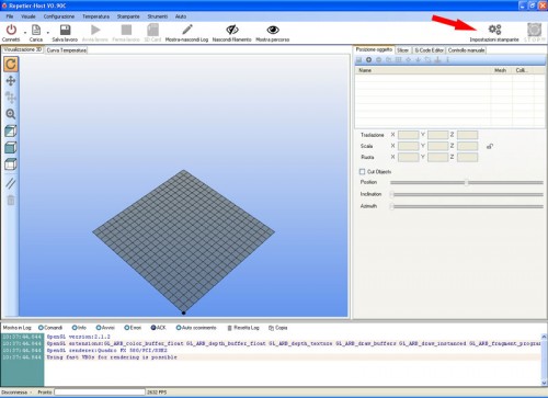
Boris Landoni shows us how to create G-Code using Eagle PCB design software:
To create a PCB with 3Drag , by milling , it is necessary to have the G-Code files for the tracks patterning and for the holes relating to the printed circuit board itself. In this section we describe how to obtain these G-Code files using a specific plugin for the popular PCB design software ” EAGLE “.
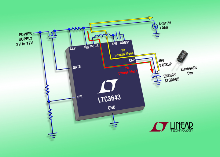
Linear Technology Corporation introduces the LTC3643, a bidirectional, high voltage boost capacitor charger that automatically converts to a buck regulator for system backup. The proprietary, single-inductor topology with integrated PowerPath™ functionality does the work of two separate switching regulators, reducing size, cost and complexity. The LTC3643 operates in two modes – boost charge mode and buck backup mode. The charging mode efficiently charges an electrolytic capacitor array up to 40V with an internal switch current rating of 2A from an input supply between 3V to 17V. In backup mode, when the input supply falls below the programmable power-fail (PFI) threshold, the step-up charger operates in reverse as a synchronous step-down regulator to power and hold up the system rail from the backup capacitor. During backup, the current limit can be programmed from 2A to 4A, making this device ideal for high energy, relatively short duration backup capacitor systems, power failure backup systems, solid-state drives and battery stack charging applications.
LTC3643 – 2A Bidirectional Power Backup Supply – [Link]
educ8s.tv shows us how to use a servo motor with Arduino UNO:
A Servo is a small device that has an output shaft. This shaft can be positioned to specific angular positions by sending the servo a coded signal. That’s why we need the Arduino, in oder to send that signal to the servo. Servos in general require a lot of current to operate since they have a motor inside. If you only need to control one small servo like this one you can connect it directly to Arduino. If you need to control two or more servos you need an external power supply or battery pack. Today we are going to use only one servo so we are going to connect it directly to an Arduino Uno. We are using an SG90 micro servo today which is a very popular one and very cheap. It costs around 3$.
Arduino Tutorial: Using a Servo SG90 with Arduino – [Link]
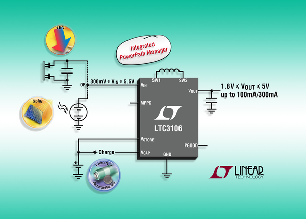
The LTC3106 is a highly integrated, 1.6μA quiescent current 300mV startup buck-boost DC/DC converter with PowerPath management, optimized for multisource, low power systems. The LTC3106 is ideal for powering low power wireless sensors from rechargeable or primary batteries supplemented by energy harvesting. If the primary power source is unavailable, the LTC3106 seamlessly switches to the backup power source. The LTC3106 is compatible with either rechargeable or primary cell batteries and can trickle charge a backup battery whenever there is an energy surplus available.The LTC3106 provides 300mA steady state and 650mA peak load current at up to 92% efficiency.
LTC3106 – 300mA Low Voltage Buck-Boost Converter – [Link]