Weller WSD81i soldering station now with a cleaning set for free

obr1789_uvod

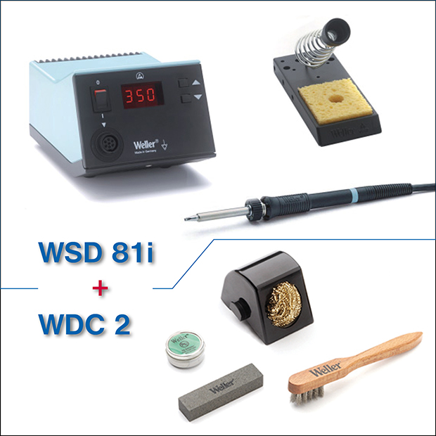
Reliable “industrial” station WSD81i for excellent price and a set with a value of 40 Eur as a free bonus – that´s our gift to you. 

Innovated soldering station Weller WSD81i was in-depth introduced to you in our article Weller WSD81i soldering station doesn´t need a calibration even after years.
WSD81i soldering station hides behind a relatively plain classic design a top level technique. WSD81i uses „Silver line“ technology of a heat transfer to a relatively short tip with a copper core, ensuring excellent heat transfer and excellent temperature accuracy.

Briefly:

  •  platinum thermal sensor, doesn´t require calibration even after a long-term operation (IPC compliant).
  • standby mode (adjustable in a range of 1-99min) and electronics controlling usage of a soldering tool
  • “Offset” function for a change of a displayed temperature ( advantageous for example in plants, where workers were used to set say 380°C but at WSD81i even 360°C would be sufficient (thanks to excellent heat transfer to a tip). In this case a worker doesn´t have to differ which soldering station he uses and he can use a unified setting for all types
  • possibility to lock the station by your own code
  • possibility to set a temperature “window”
  • uses modern and economical tips from the LT series

Comparison of three main technologies and also a comprehensive description of particular tips can be found in the “Weller soldering tips” brochure. Detailed description of the WSD81i station can be found in the WSD81i user guide.
WSD81i – namely version T005 32 946 99 (80W tool + wet cleaning stand) is brought to you in a special offer, where besides attractive price (259 Euro) you´ll gain a quality tip cleaning set with a value of 40 Euro for free.

The cleaning set (WDC2 dry cleaner, T0051512799) contains a stand for dry cleaning, polishing bar, stainless steel brush and tip activator. Thanks to this set you can significantly prolong lifetime of your tips and concretely this set also enables you to choose dry or wet cleaning according to your current requirements.
For 259 Euro you´ll get a complete soldering station and perspectively – you can choose from the LT series tips or from any other accessories, including soldering fumes extraction stations (non-stock types we´re able to deliver you upon request with a short leadtime).

Weller WSD81i soldering station now with a cleaning set for free – [Link]

SparkFun: A look inside some common power supplies

molex_topside

MTaylor @ sparkfun.com takes a look inside different power supplies he has on his box.

Power supplies are everywhere these days. With the advent of switching power supplies, the cost of high-current supplies has radically dropped. Maybe you’ve noticed how the large, heavy, wall-wart style adapters are no longer lurking around your baseboards, falling out of their sockets? Or occupying several of your valuable power-strip positions? But not all power supplies are created equal.

SparkFun: A look inside some common power supplies – [Link]

SRF01 Sensor teardown and reverse engineering

andur

Jaanus Kalde wanted to know why his SRF01 sensor fails after dropping from the air so he did a reverse engineering on it.

I needed small ultrasonic sensors for a flying sensor. So I got the smallest one – SRF01. Quite nice unit, works down to 0 cm. There were some problems with it – Maximum detection frequency is only ~14 Hz and the resolution isn’t so great (1 cm). Also, on some occasions after falling from a high height the transducers broke and sensor would only give out constant distance reading. To fix the broken sensors (which I had many) and to satisfy my curiosity I took one apart and reverse engineered it.

SRF01 Sensor teardown and reverse engineering – [Link]

Little Helper: an ARM powered mobile device

Oben_Komplett-e1450110377624-750x410

Phillip Schuster has build a portable device featuring some ports to connect stuff like sensors and other circuits and some menu driven user interface to trigger various modules doing tests, reading data etc.

Working in my lab with electronics I came across different little challenges once in a while, and noticed that I am missing tools to handle them efficiently. Just a quick list, I am sure you could add various items to the list:
What is the I2C address of a chip? (yeah, you can work through the Datasheet but the Datasheets I know don’t have an outline topic for this. It’s somewhere hidden deep in text somewhere)
What is the voltage range of the analog sensor in my current environment (take a photo sensor)?
Generating PWM or DAC signals
Does this circuit do anything?
Does this circuit do anything specific?
Reading serial output of your Microcontroller/Arduino project

Little Helper: an ARM powered mobile device – [Link]

Switch Mode Power Supply (SMPS) Topologies (part I)

apps

Microchip’s application note describes the basics of different SMPS topologies:

The industry drive toward smaller, lighter and more efficient electronics has led to the development of the Switch Mode Power Supply (SMPS). There are several topologies commonly used to implement SMPS. This application note, which is the first of a two-part series, explains the basics of different SMPS topologies. Applications of different topologies and their pros and cons are also discussed in detail. This application note will guide the user to select an appropriate topology for a given application, while providing useful information regarding selection of electrical and electronic components for a given SMPS design.

Switch Mode Power Supply (SMPS) Topologies (part I) – [Link]

Replacement LED driver for AN6877

aflevelmeter

Dilshan Jayakody has designed a board to replace AN6877 base LED drivers using discreet transistors. He writes:

AN6877 is linear AF level meter IC produced by Panasonic and it is commonly found on many audio equipment. This chip is no longer manufactured by Panasonic and finding replacement chip for AN6877 is also quiet difficult.
The circuit described in this article is design to replace AN6877 base LED drivers and it is based on commonly available components. This replacement LED driver is design using 10, MMBT3904/2N3904 transistors and it can easily modify to get necessary number of outputs.

Replacement LED driver for AN6877 – [Link]

Raspberry Pi Tutorial: Create your own GUI with TkInter and Python

educ8s.tv shows us how to build a graphical user interface on Raspberry Pi using TkInter and Python.

Having a Graphical User Interface (GUI) on a touch screen makes controlling your Raspberry Pi so much easier. With Python and TkInter one can develop his own GUI very easily. In this video we are going to see how to achieve that.

The project we are building today is very simple but very useful. As you can see I am using an application that I have developed to turn on or off the LED simply by touching an on screen button. In this video we are going to see how to develop an application like this, and as you are going to find out, it is extremely easy!
The hardware setup of today’s project is this. I am using a Raspberry Pi A+ but you can use any Raspberry Pi you want that has 40 GPIO pins. I am also using a 5 Inch touch display from Waveshare. I have prepared a detailed tutorial on that display few weeks ago, you can check it out. If you don’t have a touch display, the Graphical User Interface we are developing will work fine with a mouse as well.

Raspberry Pi Tutorial: Create your own GUI with TkInter and Python – [Link]

Tutorial on the Theory, Design and Characterization of a CMOS Transimpedance Amplifier

In this episode, Shahriar and Shayan discuss the design and characterization of a deceptively simple CMOS inverter-based transimpedance amplifier. The the large and small signal behavior of the CMOS inverter is discussed and measured using the Keithley 2450 and 2460 source meters. The transient response is also measured using a Keysight MSO-S series oscilloscope.

The small signal gain of the circuit is calculated from small signal parameters which are extracted directly by measuring the devices I/V characteristics. The NMOS/PMOS devices used are from an ADL1105 quad-discrete transistor IC. Through the use of a shunt-shunt feedback, the CMOS amplifiers is converted to a transimpedance amplifier which is capable of amplifying the current from a photo-detector diode by a gain of 30kV/A. The feedback theory is used to calculate the gain of the amplifier. The slides for this tutorial can be downloaded from The Signal Path website.

Tutorial on the Theory, Design and Characterization of a CMOS Transimpedance Amplifier – [Link]

LT3091 – –36V, 1.5A Negative Linear Regulator with Programmable Current Limit

3091

Linear Technology Corporation announces the LT3091, the latest addition to our LDO+ family, a 1.5 A low dropout negative linear regulator featuring low noise, rail-to-rail operation, precision programmable current limit and a bidirectional output current monitor. The device is cable-drop compensation capable, easily paralleled for higher current or circuit board heat spreading, and configurable as a 3-terminal floating regulator. The LT3091’s input voltage range is –1.5 V to –36 V. A single resistor programs the adjustable rail-to-rail output voltage from 0 V to –32 V and dropout voltage is only 300 mV (typical at full load).

LT3091 – –36V, 1.5A Negative Linear Regulator with Programmable Current Limit – [Link]

Dual Motor L298 H-Bridge Motor Control

IMG

Dual Motor L298 H-Bridge Control project can control two DC motors connected to it. The circuit has been designed around popular dual H-Bridge L298 from ST. This circuit has current sense resistors for both H-bridges to provide voltage which enables this board to use in stepper motor applications.

Specifications

  • Motor supply : 7 to 46 VDC
  • Control Logic Supply : Standard TTL logic level
  • Output DC drive to motor : up to 2 A each
  • Current Sense Output available
  • Enable and direction control pins available
  • External diode bridge for protection
  • Heat-sink for IC
  • Power-On LED indicator
  • Screw terminal connector for easy input supply (PWR) / output (Motor) connection
  • Four mounting holes of 3.2 mm each
  • PCB dimensions 61 mm x 63 mm

Dual Motor L298 H-Bridge Motor Control – [Link]

TOP PCB Companies