Dual Motor L298 H-Bridge Motor Control

IMG

Dual Motor L298 H-Bridge Control project can control two DC motors connected to it.  The circuit has been designed around popular dual H-Bridge L298 from ST. This circuit has current sense resistors for both H-bridges to provide voltage which enables this board to use in stepper motor applications.

Specifications

  • Motor supply : 7 to 46 VDC
  •  Control Logic Supply : Standard TTL logic level
  •  Output DC drive to motor : up to 2 A each
  •  Current Sense Output available
  • Enable and direction control pins available
  •  External diode bridge for protection
  •  Heat-sink for IC
  •  Power-On LED indicator
  •  Screw terminal connector for easy input supply (PWR) / output (Motor) connection
  •  Four mounting holes of 3.2 mm each
  •  PCB dimensions 61 mm x 63 mm

Schematic

SCH

Parts List

BOM

Connections

Connections

Arduino MKR1000 – 32-bit board with WiFi

MKR1000_web

The MKR1000 development board from Arduino provides a simple way to add wireless connectivity to IoT battery-powered projects.

Arduino MKR1000 is based on the Atmel ATSAMW25 SoC (System on Chip), that is part of the SmartConnect family of Atmel Wireless devices, specifically designed for IoT projects and devices.

The ATSAMW25 is composed of three main blocks:
• SAMD21 Cortex-M0+ 32bit low power ARM MCU
• WINC1500 low power 2.4GHz IEEE® 802.11 b/g/n Wi-Fi
• ECC508 CryptoAuthentication
The ATSAMW25 includes also a single 1×1 stream PCB Antenna.

Arduino MKR1000 – 32-bit board with WiFi – [Link]

ATiny does 170×240 VGA with 8 Colors

main

AtomicZombie @ avrfreaks.net used an ATtiny85 ATMEL microcontroller to produce a 170×240 VGA signal and also send audio along with video.

The original plan was to just bit bang some mono VGA and do up a Pong or Tetris game, but things went MUCH MUCH further than I ever thought possible, so over the next few weeks I will detail this fun project here. I call it The QUARK-85 VGA DEMO System.

So what can one do with an ATTINY-85 and no other external components, an 8 pin package that leaves ONLY 4 IO lines after you feed it a clock??

How about 4 color rock solid VGA with stereo sound!!!

ATiny does 170×240 VGA with 8 Colors – [Link]

Raspberry Pi Zero Information Display

IMG_0477-950x713

Frederick @ frederickvandenbosch.be has build an Internet connected OLED display using Raspberry Pi Zero module.

After last week’s Pi Zero mod, I thought I’d try a slightly more useful project. Using an Adafruit OLED display, two push buttons, a wifi dongle and a Pi Zero, I made an internet connected information display. The information could be anything: time and date, weather, social media status, etc … The two push buttons are used to cycle through the data and trigger certain actions.

Raspberry Pi Zero Information Display – [Link]

DIY I2C LCD Display

FKPROHGII94PPRL.LARGE

sspence @ instructables.com shows how to interface a character LCD using I2C and only two IO pins.

The typical parallel LCD used with an Arduino (16×2 or 20×4) has 16 pins. Only 6 I/O pins are required on the Arduino, but what if you could get that down to two I/O pins, and still have those pins available for other devices?

The I2C interface is on pins A4 and A5 of the Arduino. These are addressable, and are therefore shareable with other I2C devices that have different addresses.

DIY I2C LCD Display – [Link]

FUN but REAL: Manually or lying down

obr1802_uvod

Yes, these are your options when you want to set time relay of 12.51 series from Finder producer.

Italian producer accommodated less active installers that can now set, resp. program time relay also lying down. Of course, something for something – you need to have a computer but luckily it is something that almost any installer has in his pocket – a smartphone supporting NFC. So, how does it work and what needs to be done:
● Select the appropriate moment – it can be even in the middle of the night
● Choose a comfortable bed – empty one would be the best, so you don’t get distracted by anything
● Put on a comfy clothes – even dungarees, but in that case we suggest covering the bed with polythene
● For the first time, you need to be able to connect to wi-fi from the bed so you can easily download free app FINDER Toolbox from the GooglePlay.

Lay comfortably down – the most well-known and used positions are these four:

  • on the back
  • on the belly
  • on the side version L (on the left)
  • on the side version R (on the right)

In case of using a polythene, you can use all four positions also with legs on the pillow

  • The work itself is just a “game on the phone”
  • Start the game FinderToolbox. Set when and for how long you want that thing to be on and save the settings.
  • The most difficult phase of programming is about to get started. Get off the bed, come to the time relay and touch the actual time relay with your smartphone – that’s when the settings will be transferred to relay

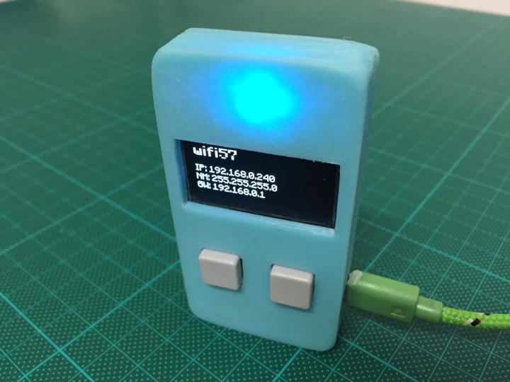
Time relay 12.51 looks like an ordinary time relay on a DIN rail with big nice display backlight – blue signs on white background that effectively shows the necessary information.

Relay also allows programming with joystick (thus manually). This mode is for those who cannot relax while working.


FUN but REAL: Manually or lying down – [Link]

Light To Audio Oscillator

B004

Light Sensitive Audio Oscillator project is a fun loving project which will create different sound effects depending on the light falling on the sensor

Specifications

  • Supply input 5 ~ 12 VDC
  • Output 8 Ohms, 0.5 W Speaker
  • Terminal pins for supply voltage and speaker connection
  • Power-On LED indicator
  • PCB dimensions 38 mm x 44 mm

Light To Audio Oscillator – [Link]

Light To Audio Oscillator

B004

Light Sensitive Audio Oscillator project is a fun loving project which will create different sound effects depending on the light falling on the sensor

Specifications

  • Supply input 5 ~ 12 VDC
  • Output 8 Ohms, 0.5 W Speaker
  • Terminal pins for supply voltage and speaker connection
  • Power-On LED indicator
  • PCB dimensions 38 mm x 44 mm

Schematic

sch

Parts List

bom

Meet ESP32, New Big Brother to IoT Board ESP8266

ESP32

Alasdair Allan @ makezine.com discuss about a new IoT board released from the company that makes the ESP8266.

The ESP8266 chip, and the boards based around it, have been the new hot new thing this past year. Overnight it became — almost by stealth — one of the leading platforms for the Internet of Things. This runaway success quickly gathered a community, and it’s possible Espressif Systems may repeat that next year with their new ESP32 chip.

Meet ESP32, New Big Brother to IoT Board ESP8266 – [Link]

TOP PCB Companies