LT8331- Low IQ Boost/SEPIC/ Flyback/Inverting Converter

8331

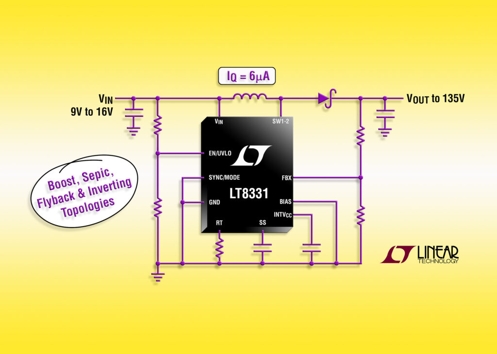
The LT8331 is a current mode step-­up DC/DC converter with an internal 500mA, 140V switch. It operates from an input voltage range of 4.5V to 100V, making it suitable for use with a wide range of input sources found in industrial, transportation and avionic applications. The LT8331 can be configured as either a boost, SEPIC, flyback or inverting converter. Its switching frequency is programmable from 100kHz to 500kHz, enabling designers to minimize external component sizes. Burst Mode operation reduces quiescent current to only 6µA while keeping output ripple below 20mV. The combination of a high voltage MSOP­-16E package and tiny externals ensures a very compact footprint while minimizing solution cost.

LT8331 – Low IQ Boost/SEPIC/ Flyback/Inverting Converter – [Link]

Voice Changer

B011-500x500-500x500

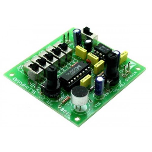
Voice Changer project can be used to transpose or distort one’s voice by encoding the sound appearing at the Microphone input. This project is built around AP8072 IC.

Specifications

  • Supply input : 6 VDC @ 200 mA
  • Output : Speaker, 8 Ω / 0.5 W
  • Audio amplifier type LM386 with volume control preset
  • Jumper selectable tone frequency for encoding sound
  • 4 Tones to choose
  • Built in noise reduction circuit for reducing environment noise
  • On/Off Jumper connector for power supply input
  • Berg connector for power supply input and speaker output
  • Four mounting holes of 3.2 mm each
  • PCB dimensions 48 mm x 52 mm

Voice Changer – [Link]

Voice Changer

B011-500x500-500x500

Voice Changer project can be used to transpose or distort one’s voice by encoding the sound appearing at the Microphone input.  This project  is built around AP8072 IC.

Specifications

  • Supply input : 6 VDC @ 200 mA
  • Output : Speaker, 8 Ω / 0.5 W
  • Audio amplifier type LM386 with volume control preset
  • Jumper selectable tone frequency for encoding sound
  • 4 Tones to choose
  • Built in noise reduction circuit for reducing environment noise
  • On/Off Jumper connector for power supply input
  • Berg connector for power supply input and speaker output
  • Four mounting holes of 3.2 mm each
  • PCB dimensions 48 mm x 52 mm

Schematic

sch

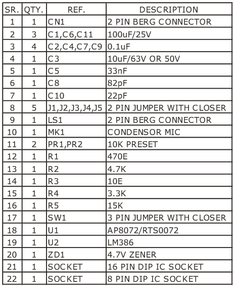
Parts List

bom

Jumper Settings

jumper

DIY SWR and Power Meter

Meter0

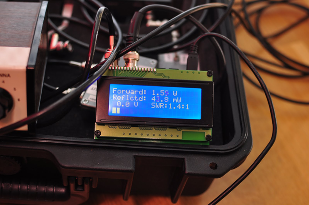
diycrap.blogspot.com has build a SWR and power meter based on Arduino Nano and LCD display:

First of all, this SWR meter in this article is not exactly homebrew, as I based the circuit on the schematic in the excellent book Arduino Projects of Amateur Radio. Although I bought the book and respect the copyright of the authors I will share my own schematic here. Why? First, the design in the book is not completely original and is based on similar designs from others. One example here. Second, I changed a few things, removed some stuff, and added some other things, to my own liking, so the design is not identical anymore.

DIY SWR and Power Meter – [Link]

Nandland Go Board – Your FPGA Playground

FPGA_Board

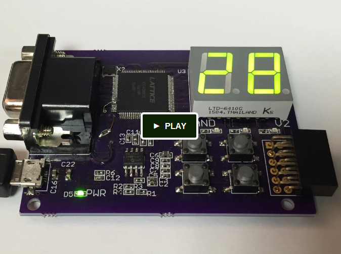
There’s a new FPGA development board on Kickstarter. It’s called the Nandland Go Board, and it aims to be an inexpensive, easy-to-use FPGA development board to learn about how FPGAs work and what they are capable of. This board is unique because it provides a lot of options for projects built directly into the board. It comes with:

  • Four LEDs
  • Four Push-Button Switches
  • Two 7-Segment LED displays
  • Micro USB Connector (for Programming and Communication)
  • VGA Connector
  • External Connector

Most other FPGA development boards come with just a simple connector but the Go Board has lots of functionality built right into it. The Kickstarter page shows a bunch of examples of what is possible using the Nandland Go Board, and it’s pretty impressive. You can even program it to play Pong! Take a look at the Kickstarter page and pick one up today.

Nandland Go Board – Your FPGA Playground – [Link]

Universal shield for popular platforms Raspberry Pi, Arduino, Intel Edison

DSC_0539_01-750x330

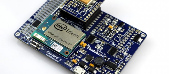
Modulowo DuoNect™ is a universal solution for rapid prototyping and production that allows easy connection of expansion modules, such as sensors, controllers, buttons, analog and digital IC, GPS, Bluetooth, WiFi (and more) for platforms, such as, Intel® Edison, Raspberry Pi, Arduino, Genuino, STM32 Nucleo, TI LaunchPad, Atmel Xplained or Freescale Freedom / Kinetis.

Specifications:

  • standard pinout including the power pins, UART, I2C (TWI), SPI, 1-Wire, digital and analog pins
  • width (~ 25.6 mm, 1010 mils)
  • 3.3V/5V logic levels tolerant
  • compatibility with breadboard
  • possibility of installing a identification chip
  • can be installed directly on adapters by castellated holes or by pin headers

Universal shield for popular platforms Raspberry Pi, Arduino, Intel Edison – [Link]

Power Management of Xilinx ZedBoard using MMPF0100

This reference design is a power management of Xilinx ZedBoard using MMPF0100 Power Management Integrated Circuit (PMIC). A PMIC is an IC for managing power requirements of the host system and is commonly used in a system-on-chip (SoC) device. On the other hand, the Xilinx ZedBoard, a development board based on Zync-7000 AP SoC, provides appropriate hardware capabilities for interfacing with a number of peripherals and compatible expansion headers for Xilinx Analog to Digital Converter (XADC), FPGA Mezzanine Card (FMC) and Digilent Pmod.

This design utilizes the Freescale’s MMPF0100 PMIC. The 12V from a barrel-jack connector, which supplies the Zedboard, must be stepped down to 3.6V in order to meet the input supply requirement of the MMPF0100. The MMPF0100 provides a highly programmable/ configurable architecture, with fully integrated power devices and minimal external components. The buck regulators in the PF0100 may be configured as five independent regulators to power VCCINT, VCCAUX, VCCO2, VCCO_DDR and VTT_DDR rails. This allows the VTT_DDR rail to automatically track half of VCCO_DDR if they are connected to SW4 and SW3A respectively. The boost regulator in the PF0100 is utilized to supply the VCC5V0 rail. The VCCO1 rail requires a buck converter to convert the available 3.6V to 3.3V, while being capable of supplying 3A. Because most peripherals are supplied through this rail, the current being drawn may vary. Therefore, to ensure safe operation, both this rail and the VCCINT rail are provided with sufficient margins. The Freescale Switched-mode Power Supply (SMPS) MC34713 provides a good option for achieving this. The MC34713 is a highly integrated, space efficient, low cost, single synchronous buck switching regulator with integrated N-channel power MOSFETs.

PMICs minimize energy loss, and hence, they are useful in mobile devices, televisions, and cars. With up to six buck converters, six linear regulators, RTC supply, and coin-cell charger, the MMPF0100 can provide power for a complete system, including applications processors, memory, and system peripherals, in a wide range of applications.

Power Management of Xilinx ZedBoard using MMPF0100 – [Link]

Tiny Mic Preamplifier

A017

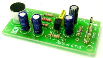
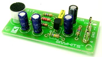
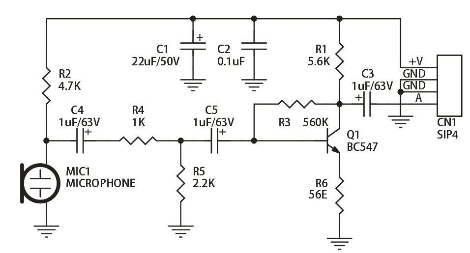
The Tiny Mic Preamplifier based is based on a single transistor amplifier design.  It amplifies the output of the electret condenser microphone.  Good choice for Karaoke.

Specifications

  • Power supply: 5 ~ 9 VDC @ 2 mA
  • Provides standard audio signal
  • PCB dimensions 26 mm x 56 mm

Schematic

SCH

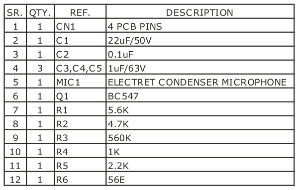
Parts List

BOM

Pull-up Resistors explained

511568b6ce395f1b40000000

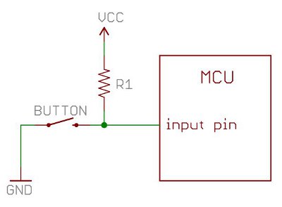
a1ronzo @ learn.sparkfun.com explains us the importance of pull-up resistors and when and why they are used in digital circuits.

Pull-up resistors are very common when using microcontrollers (MCUs) or any digital logic device. This tutorial will explain when and where to use pull-up resistors, then we will do a simple calculation to show why pull-ups are important.

Pull-up Resistors explained – [Link]

TOP PCB Companies