Automation is defined as using various control systems to operate equipment such that there is minimal human intervention. Closed control loops (feedback systems) regulate how other systems or devices behave by taking into consideration their output and making corrections based on feedback. An example of this feedback system is Progressive Automation Linear Actuators. In this article challenges of control loops in wireless systems are discussed.
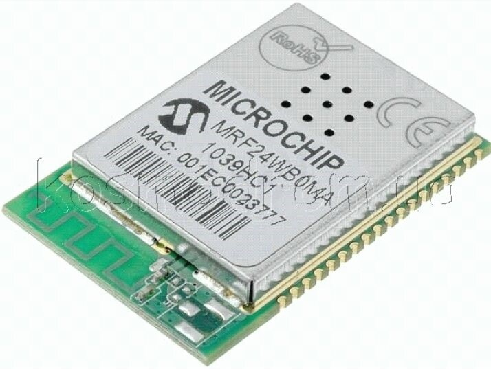
Though embedded modules can be used be used with Wi-Fi, the aim of recent protocols is providing wireless networks with more focused support for control loops. For tight control loops, devices supporting the IEEE802.15.4 ZigBee standard can be used in supporting the recent protocols. Below is a Microchip’s MRF24WB Wi-Fi module.
For sharing a common medium of communication, sensors and controllers are required by a control system that is adopting wireless communication. The network’s quality is a trivial part of the functioning of the overall system when implementing a closed-loop control system using a common communication system.
Earlier short range wireless networks pose a problem since delay deadlines are not used in packet consideration and regardless of these requirements, the packets are treated the same. For a closed loop control system, this presents a major challenge since actuators influencing the system are controlled by the sensor’s data. Data delays lead to negative reinforcement, hence instead of a process being kept within close limits, it runs away. Continue reading “Control Loop Challenges of Wireless Systems”
SteelCity Electronics published an article about Analog Devices AD587KN 10V reference:
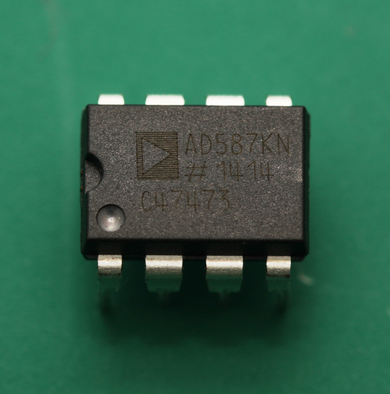
I recently got hold of an Analog Devices AD587KN high precision 10.000V reference chip.
This model of chip has an output value of 10.000V ± 5mV (that is, an output value of 9.995V to 10.005V) straight out of the factory. A voltage drift of 10ppm/°C at 25°C meaning that the output voltage will drift by 10μV for each 1°C the chip is exposed to. Additionally, the chip has a voltage trim input, so if you have access to a precision voltmeter, the chip’s output value can be adjusted even closer to 10.000V.
Alternatively, the chip’s output can be trimmed to a value of 10.24V. You may think that a value of 10.24V seems like a strangely familiar number. A value of 1024 is the decimal representation of 10bits, that is 2∧10 = 1024. Why would I want a voltage reference that outputs a value of 10.24V? Because it makes any ADC or DAC conversions much simpler.
Analog Devices AD587KN 10V reference chip – [Link]
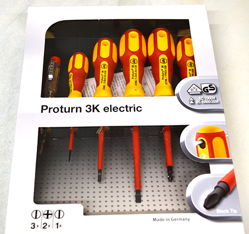
Wiha Proturn® screwdrivers enable a comfortable work, even in case you need to gain a high torque.
As we know, the “power” (torque) we´re able to reach by a common screwdriver depends mainly from two factors – from a screwdriver handle size and design and – from our own strength :-). Strength of our hand can be changed only by hard training but a screwdriver intended to gain a maximu “power” is available immediately. The Proturn series from compant Wiha is one of suitable series for this purpose. Series Proturn features a robust two-component handle, with parts made of hard plastic and a soft rubber resulting in a very good grip. Quality chrome-plated and through hardened CrVMo steel guarantees long lifetime.Practical opening in a handle enables comfortable and well-arranged hanging on a wall of your workshop. They´re suitable for all works on electrical devices up to 1000V AC/ 1500VDC (VDE and GS approval). Each screwdriver is individually tested according to IEC60900:2004. Directly from our stock we´re able to supply to you price-advantageous set 470N K601 containing 5 Proturn 3K electric screwdrivers (2,5×75/ 4,0×100/ 5,5×125/ PH1x80/ PH2x100) and one classic voltage tester.
Any other tools from Wiha we´re able to supply to you upon request in a short leadtime and at favourable conditions.
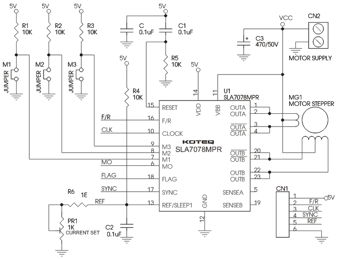
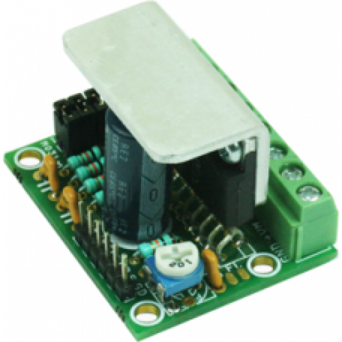
This tiny Unipolar stepper motor driver has been designed around SLA7078MPR IC from Sanken, It is unipolar stepper Motor driver can handle current up to 3 Amps, micro-stepping up to 1/16 steps. On-board Jumpers to set the Micro-stepping, Preset (Potentiometer) to set the current.
The SLA7070MPR series motor driver ICs features unipolar drivers. The clock-in type input interface allows simplified control logic, and options for built-in sense current detection and load circuit short or open protection (patent pending) provide lower loss, and lower thermal resistance.
The built-in excitation distribution circuit (sequencer) allows motor control using only the CLOCK signal for simple operations (rotate/stop), with motor speed control by frequency input into CLOCK pin. This eliminates logic signal lines required for conventional phase-input methods, and reduces demand on heavily-used CPUs.
Unipolar stepper board is high efficient stepper driver for Unipolar stepper motor been design for various application like robotics, control routers, lathes, mills, PCB drillers and engravers.
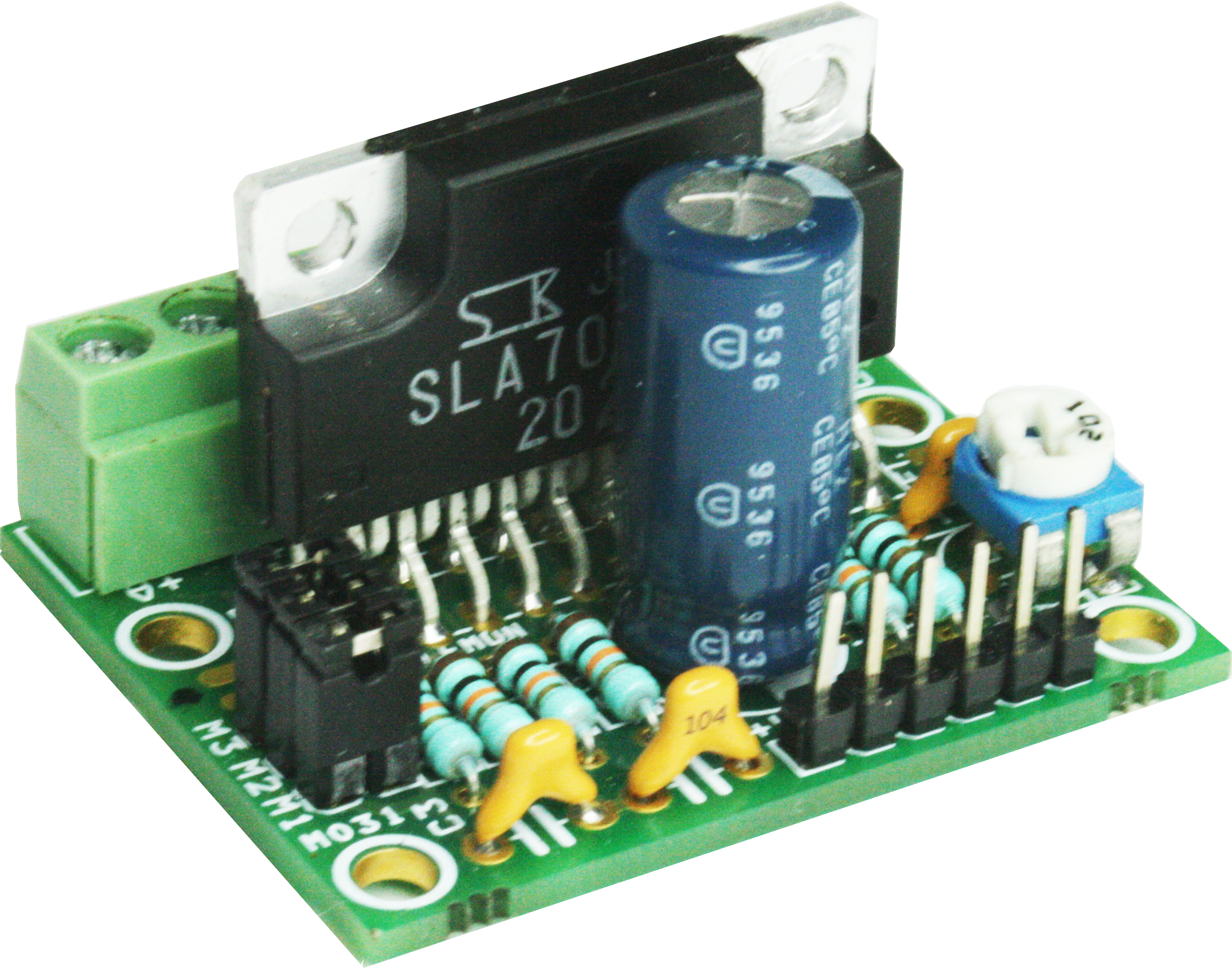
This tiny Unipolar stepper motor driver has been designed around SLA7078MPR IC from Sanken. It is a unipolar stepper Motor driver that can handle current up to 3 Amps and has micro-stepping up to 1/16 steps. On-board Jumpers are available to set the Micro-stepping and Preset (Potentiometer) to set the current.
The SLA7078MPR series motor driver ICs features unipolar drivers. The clock-in type input interface allows simplified control logic, and options for built-in sense current detection and load circuit short or open protection (patent pending) provide lower loss, and lower thermal resistance.
The built-in excitation distribution circuit (sequencer) allows motor control using only the CLOCK signal for simple operations (rotate/stop), with motor speed control by frequency input into CLOCK pin. This eliminates logic signal lines required for conventional phase-input methods, and reduces demand on heavily-used CPUs.
Unipolar stepper board is a high efficient stepper driver for Unipolar stepper motor and it has been designed for various application like robotics, control routers, lathes, mills, PCB drillers and engravers.
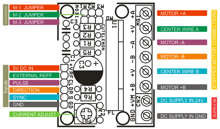
This board has been designed to be used in two ways, Stand Alone and Microcontroller Interface or Auto Half Current.
Stand Alone
Just to Rotate Motor normally bellow inputs required:
Pulse (Step Pulse In) Frequency
Direction
5V DC
GND
SYNC and REF doesn’t Required for this operation.
Microcontroller Interface or Auto Half Current
For Micro-Controller Interface or Auto Half Current (while Motor is in Hold-State):
Usually In Motion control and CNC application stepper motor driver required auto Half Current function specially while motor is not moving and it’s in hold-state. For this operation SYNC and Ref required input signal.
SYNC input is for chopping synchronous function to protect from abnormal noises that may occasionally occur during the Motor Hold-State. This function can be operated by setting SYNC pin at high level.
Ref/Sleep1 – To set the half current in Motor Hold State this pin required appropriate voltage input. Also this pin can be use to driver in to sleep mode by just applying High level to this pin.
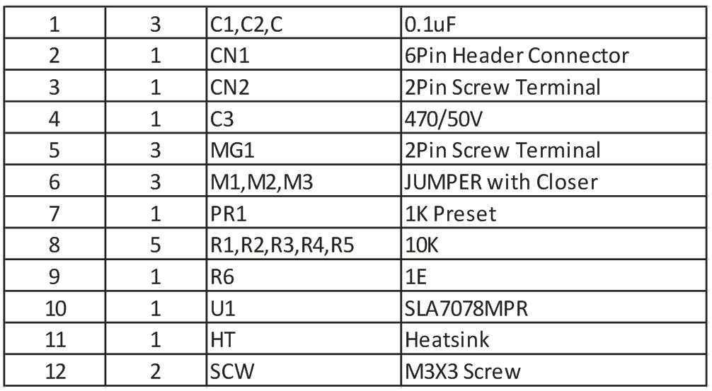
10 Pin Header connector for signal inputs, Step, Dir., 5V, Sync, V Ref./Sleep
Reference Voltage VS Output Current: 0.1V to 0.45V, 0-3Amps
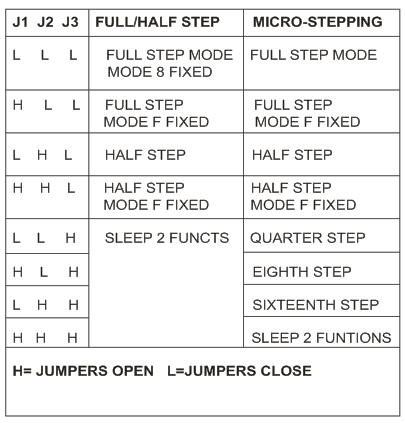
Micro-stepping via on board jumper settings
Micro-stepping possible : Full Step, Half Step, 1/4th Step, 1/8 Step 1/16 Step
Onboard preset for current adjustment
Supply input and stepper connection via screw terminal connector
Inbuilt fault protections in ic for over temp and short circuit
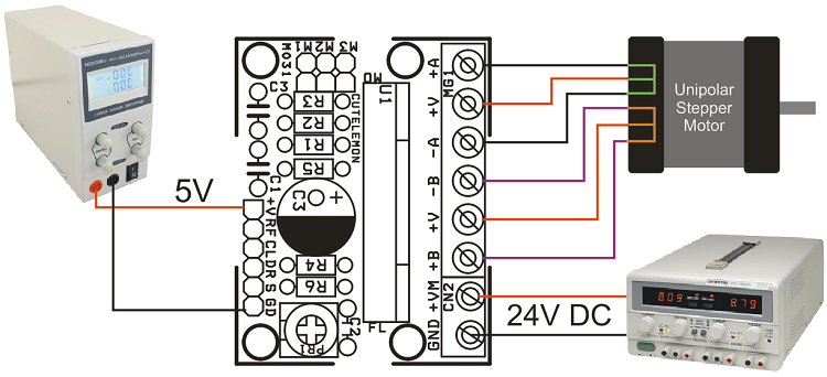
Power supply 12-42 VDC @ 3 A
For Normal Operation, V Ref. should be less than 1.5V, Applying a voltage greater than 2.0V ( High level) to VREF pin disables the drive and puts the motor in free state (Coast)
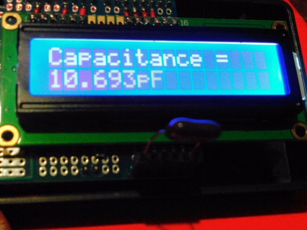
This project lets you measure capacitors in an alone range of measure from 0.000pF to 1000uF. That is, a 16×2 LCD Display will be displaying a sole scale from 0.000pF to 1000uF whose main components will be an Arduino Uno and a 16X2 LCD Display.
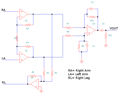
Our body is built with biological tissue. The tissue that can generate or detect bioelectrical signals is called excitable tissue. Some examples of this tissue (and its cells) are: neurons and muscular tissue. Neurons are responsible of transmitting the excitatory bioelectrical signal to another neuron (forming nerves) or to a muscle tissue, gland or brain, while muscular cells are responsible of muscular contraction and distension. Some specialized cells generate bioelectric signals: optic receptors (eyes), muscular cells that transmit the feeling of pain, etc. Bioelectricity concerns the magnetic and electrical fields produced by organisms or cells.
A teardown & analysis of a Keysight InfiniMax III N2802A 25GHz active probe from TheSignal Path:
In this episode Shahriar takes a close look at one of Keysight (Agilent) InfiniMax III active probes. The model N2802A offers 25GHz of analog bandwidth, 17.5pS of rise time and a total differential input capacitance of 32fF at 10k-Ohm input impedance. The front-end amplifier of this active probe is designed in an in-house InP process, the same process responsible for the front-end of the X-Series Keysight oscilloscopes.
The teardown of the probe shows the control circuitry in the main probe body built around a PIC 16F877 microcontroller coupled to a DAC, EEPROM memory and various high-current and precision op-amps for biasing. The main front-end microwave module reveals the InP ASIC and supporting microwave circuity. There seems to be a dual-path design to provide a large DC common-mode offset capability as well as a high-bandwidth.
Teardown & analysis of a Keysight InfiniMax III N2802A 25GHz active probe – [Link]
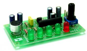
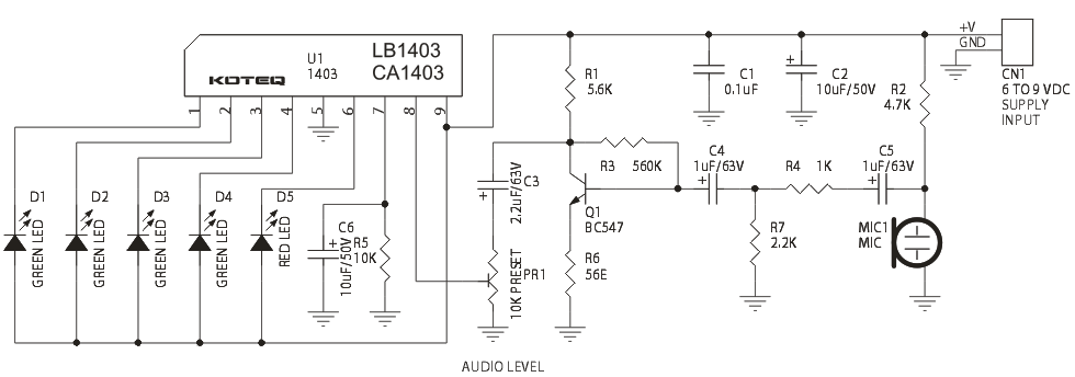
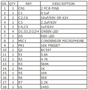
Audio Dancing LED project is a fun filled project which generates a LED dancing sequence depending on the audio level it senses. This project is based on one of the VU Meter IC LB1403 or CA1403
Audio Dancing LED project is a fun filled project which generates a LED dancing sequence depending on the audio level it senses. This project is based on one of the VU Meter IC LB1403 or CA1403