Choosing $1 sound card for DC-capable low speed oscilloscope

miniscope_v4

Tomasz Ostrowski has tested some cheap USB sound cards as low speed oscilloscope interfaces/recorders. He writes:

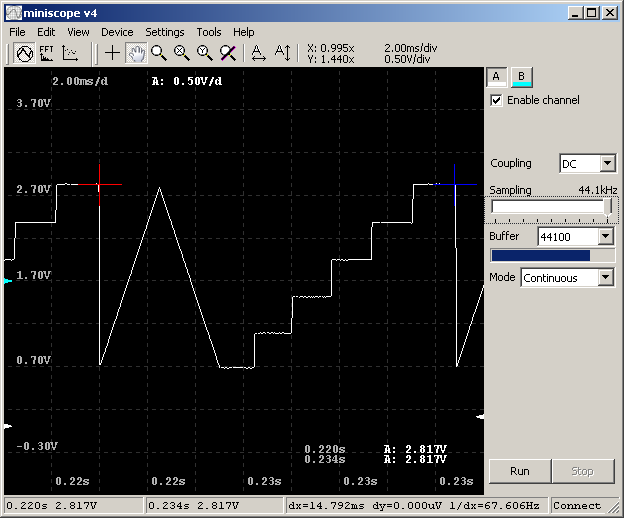
I’ve tested some cheap ($1) USB sound cards for DC sampling capability, in particular for using as low speed oscilloscope/signal recorder. Some (http://tomeko.net/dsoundscope/c_media.php or one from this thread: http://www.elektroda.pl/rtvforum/topic3106124.html) don’t seem to work despite removing DC blocking capacitor, but this one: http://tomeko.net/dsoundscope/C_Media2/ is fine. With just 120k resistor connected it is able to measure voltage from 0-6V range (cons: its input is at 2V level, sourcing 8uA if connected to GND and it’s single channel only). For test purposes I’ve prepared DLL interface for miniscope v4 (Win32 oscilloscope GUI) calibrated for this particular setup (example traces available).

Choosing $1 sound card for DC-capable low speed oscilloscope – [Link]

CCS811 – Digital CMOS gas sensors for wearables & IoT

151105edne-cambridgecmos

by Graham Prophet @ edn-europe.com:

Cambridge CMOS Sensors is a semiconductor company that designs gas sensor solutions to monitor the local environment; its CCS811 is the first digital product in its CCS800 product family of ultra-low power miniature gas sensors.

The CCS811 integrates a metal oxide gas sensor with a microcontroller sub-system which enables Indoor Air Quality Monitoring, ease of design, extended battery life and reduced system cost for smartphones, wearables and connected home devices. It is based on CCS’s Micro-hotplate technology which enables a highly reliable solution for gas sensors, very fast cycle times and a significant reduction in average power consumption compared with traditional metal oxide gas sensors.

CCS811 – Digital CMOS gas sensors for wearables & IoT – [Link]

Using The Arduino Serial Plotter

idogendel.com introduces us the new serial plotter feature of Aruino IDE 1.6.6:

A little unofficial introduction to the Serial Plotter, introduced in the Arduino IDE version 1.6.6. This is a very basic and easy-to-use tool, that allows us to set up quick visualizations of numeric data for whatever purpose.

Using The Arduino Serial Plotter – [Link]

Ovenized crystal oscillator frequency stability

alldata_20062015

E. Schrama @ ejo60.wordpress.com uses an Arduino and a DCF77 time signal receiver to test the stability of an ovenized crystal oscillator running at 1 MHz.

In this experiment I will use an Arduino and a DCF77 time signal radio receiver to measure the stability of an ovenized crystal oscillator running at 1 MHz. It demonstrates that 50ppb (or 50 milliHerz) can be achieved on the short term, whereby an aging effect of 0.1 ppb per day is demonstrated with a 18 month long dataset. The output of the 1MHz oscillator is fed into a 248 counter and six 74HC165 parallel in, serial out (piso) conversion ICs that are controlled by an ATMEGA 2560, the circuit is described here. With this setup running at 1 MHz you get a rollover every 10 years, the resolution is 1 microsecond. In principle you could do this also with an Arduino but I decided for this set-up since I already had most of the components left over from an earlier experiment.

Ovenized crystal oscillator frequency stability – [Link]

Non-Contact Body Temperature Meter

One of the most commonly used medical instruments nowadays is the thermometer. The thermometer is used to monitor or measure the body temperature of a sick person. The idea of creating a thermometer started from a device called thermoscope, a thermometer without a scale. Several inventors developed it until Sir Thomas Allbutt invented the first practical 6-inch medical thermometer able to sense a body temperature in five minutes. The development of the thermometer did not stop there and today, digital thermometer exists which is faster and very accurate.

This reference design is an example of a low cost non-contact digital thermometer. It only uses a microcontroller, a four digit seven segment display and an infrared (IR) temperature sensor. The concept of this design is to make the IR sensor measure the temperature of the thermal radiation emitted by the body being measured. The data acquired by the sensor will be sent to the microcontroller through the I2C bus. The microcontroller will analyze the data and then shows the body temperature on the four-digit seven-segment display.

The circuit of this reference design uses few components only and is very easy to understand. However, to make the circuit function accurately, software calibration must be implemented carefully. The whole circuit is powered by a 5V DC power supply regulated from the four 20mm coin shape batteries contained in a 120591-1 TE Connectivity battery holder. The batteries are connected in series-parallel connection to produce a 6V 480mAh source of power. With the help of a low-dropout voltage regulator, the 6V is regulated to a 5V DC supply

Non-Contact Body Temperature Meter – [Link]

ARPM: Another Raspberry Pi Microscope

FPS7O93IGIBLVZ8.MEDIUM

Dr H @ instructables.com build a Raspberry Pi based microscope using a WaveShare B-camera and plexiglass parts. He writes:

Based on the RPI camera and LEGO brick-based microscope I presented earlier ( A-Raspberry-Pi-camera-based-microscope-built-from- LEGO ) I have constructed a similar microscope build from Plexiglas parts. So you may build your microscope even w/o having a LEGO collection. What is missing so far is the adjustment gears of the LEGO version.

The maximum resolution is about 5 µm/pixel. On high resolution only a small area will be in focus and you will see an effect called chromatic abberation.

Below you will find a description of the device and the information required to build one on your own.

ARPM: Another Raspberry Pi Microscope – [Link]

DIY Sunlight Simulator – Light Therapy Light

DIY Sunlight Simulator Light Therapy Light banner

Luke Skaff @ lukeskaff.com decided to build a DIY Sunlight Simulator using wide spectrum filament lamp to be used as light therapy for Seasonal Affective Disorder. During the process he checks for various kinds of lamps and examines their light spectrum. He writes:

Sunlight simulation light boxes are commonly used as light therapy for treatment of Seasonal Affective Disorder (SAD). My mom has SAD and after seeing her wimpy light box I thought there had to be something better out there, after some research I was really surprised at the underwhelming sunlight simulator light therapy options on the market. When I started this project my parents lived in the Northern Virginia \ DC area of USA where there are many overcast days in the winter months. I love bright work lighting and lighting in general so part of me was happy that was not there was not a good option available on the market so I could be creative and make my own for her. Most light therapy boxes use fluorescent lighting which I have never liked due to its spikes in a few bands on the spectral power distribution (spectral distribution or emission spectra, discussed below). I love the full spectrum light of incandescent and halogens but to get a light bright enough to work for light therapy I needed a bulb in the 1100 watt halogen or 1500 watt incandescent range at minimum (likely much higher for ideal lumens) which is impractical in its power consumption and heat output. The best all around option is a high intensity discharge (HID) light such as a ceramic metal halide which have some of the best Color Rendering Index (CRI), spectral distribution, lifespan, and cost of any non-incandescent light source.

DIY Sunlight Simulator – Light Therapy Light – [Link]

DIGITAL PANEL METER – VOLTMETER

Digital_Panel_Meter_Photo

Digital Panel Meter performs digital processing on or conversion and display of voltages, currents, other analog signals, and pulse signals. This project is based on popular ICL 7107 IC, which is analog to digital converter and has been designed to drive 7 segment LED display. The ICL7107 is high performance, low power, 3, 1/3 digit A/D converter. Included are seven segment decoders, display drivers, a reference, and a clock. This DPM project may be used in a wide variety of configurations Full scale reading of +/- 199.9mV (200mV)

Features

  • Supply 5V DC @ 80mA.
  • Range 0 to 199.9mV (200mV)
  • Low Current consumption
  • Low input leakage current because external reference
  • Single supply operation
  • On board Jumpers for range display
  • Auto Zero and auto polarity within IC
  • Supply Input CN2 5V DC
  • Test Voltage CN1 0-200mV
  • PR1 Preset for reading calibration.

Digital Panel Meter – Voltmeter – [Link]

TOP PCB Companies