Digital Panel Meter performs digital processing on or conversion and display of voltages, currents, other analog signals, and pulse signals. This project is based on popular ICL 7107 IC, which is analog to digital converter and has been designed to drive 7 segment LED display. The ICL7107 is high performance, low power, 3, 1/3 digit A/D converter. Included are seven segment decoders, display drivers, a reference, and a clock. This DPM project may be used in a wide variety of configurations Full scale reading of +/- 199.9mV (200mV)
Features
- Supply 5V DC @ 80mA.
- Range 0 to 199.9mV (200mV)
- Low Current consumption
- Low input leakage current because external reference
- Single supply operation
- On board Jumpers for range display
- Auto Zero and auto polarity within IC
- Supply Input CN2 5V DC
- Test Voltage CN1 0-200mV
- PR1 Preset for reading calibration.
Digital Panel Meter – Voltmeter – [Link]


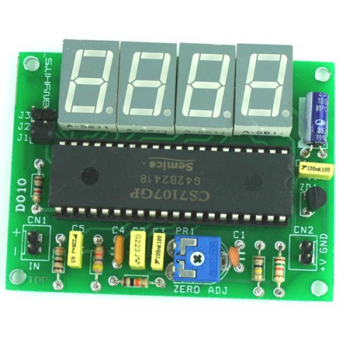
Digital Panel Meter performs digital processing on or conversion and display of voltages, currents, other analog signals, and pulse signals. This project is based on popular ICL 7107 IC, which is analog to digital converter and has been designed to drive 7 segment LED display. The ICL7107 is high performance, low power, 3, 1/3 digit A/D converter. Included are seven segment decoders, display drivers, a reference, and a clock. This DPM project may be used in a wide variety of configurations Full scale reading of +/- 199.9mV (200mV)
Features
- Supply 5V DC @ 80mA.
- Range 0 to 199.9mV (200mV)
- Low Current consumption
- Low input leakage current because external reference
- Single supply operation
- On board Jumpers for range display
- Auto Zero and auto polarity within IC
- Supply Input CN2 5V DC
- Test Voltage CN1 0-200mV
- PR1 Preset for reading calibration.
Shematic
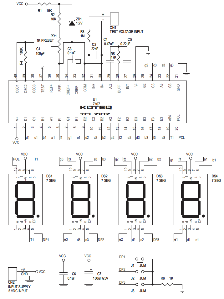
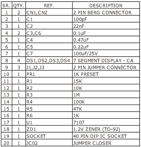
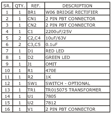
Parts List


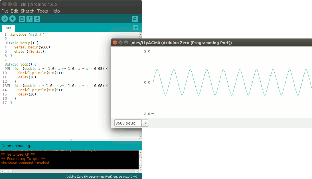
Arduino IDE latest version is ready for download. New features include the arduino-builder tool for command-line fans, a nifty Serial plotter that should help with visualizing sensor readings and tons of bug fixes. From the Arduino blog:
Today we are very proud to release Arduino IDE 1.6.6 and updated cores for all supported platforms (AVR 1.6.9, SAM 1.6.5, SAMD 1.6.2). This update brings an impressive 723 closed issues and 147 pull requests merged.
Arduino IDE 1.6.6 Now Available for Download – [Link]

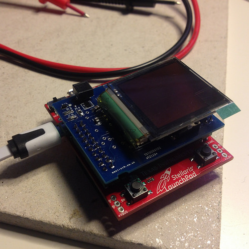
Benjamin Blundell has been working on his DIY smart-watch:
I have an issue with smart-watches. Watches in general fall into one of two categories: a tool to tell the time, or a fashion statement. Increasingly, I believe the latter category is larger than the first. With the advent of the iWatch, Pebble and the like, fashion and making a statement has moved into technology. It’s not quite a new thing but nevertheless, it’s something I’m not too fond of. My solution? Make your own smartwatch.
There is a precedent for this. Steve Wozniack sports a pretty fly nixie tube watch which he made himself. It’s pretty cool, but also a statement of sorts too. I’ve been meaning to up my game with electronics anyway, so I’ve been working on a few initial prototypes.
Building a SmartWatch – [Link]

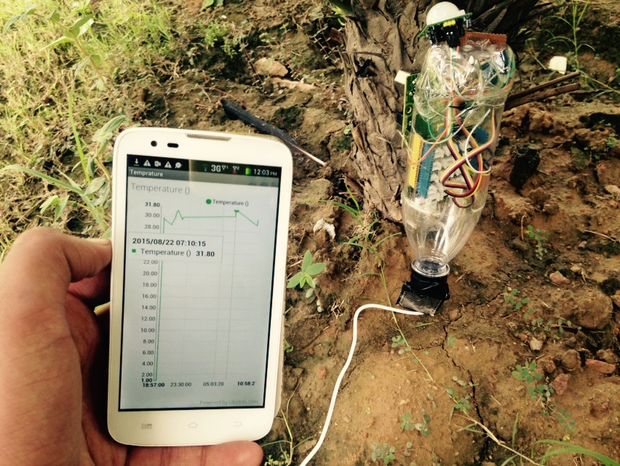
by ssarthak598 @ instructables.com:
The idea is to make a hardware + mobile app which could be used by farmers, can update farmers with any issues with their farms and can analyse amount of sunlight, rain, soil moisture, pH and can suggest best fertilizers according to the data from the sensors. It can also compare the data with the local weather data for that GPS location. The app will also have real-time updated selling prices of crops for the farmer.
Real Time Monitoring Of Crop Health using Intel Edison – [Link]


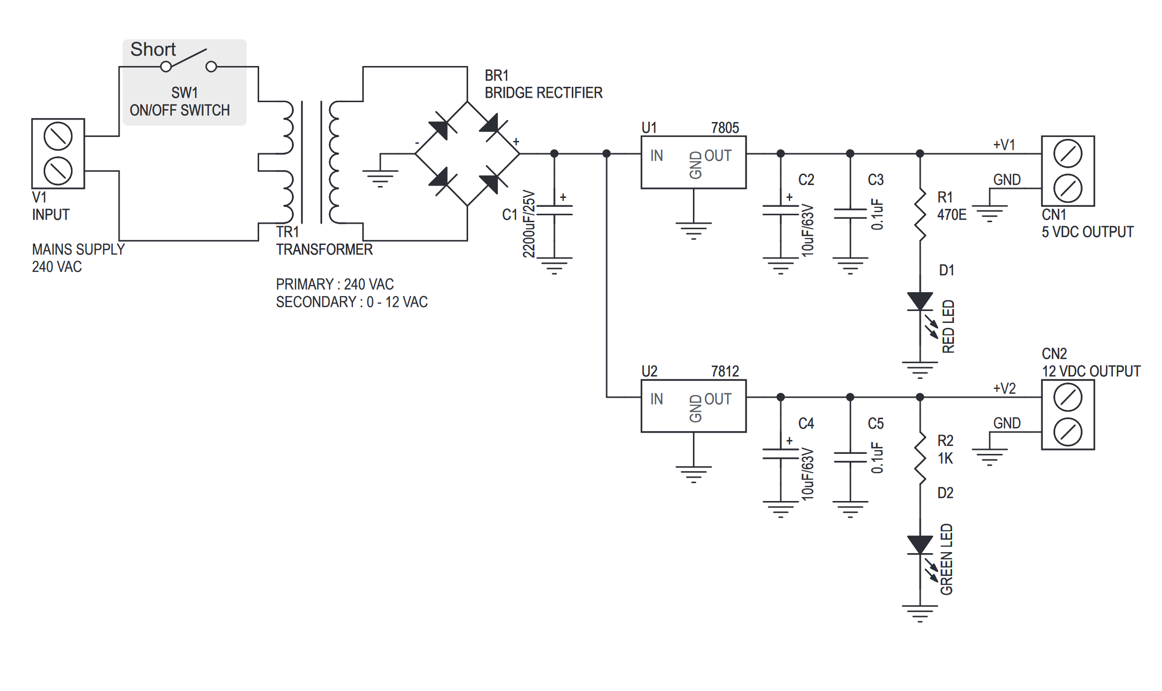
This project can be used to power up TTL and CMOS based projects, it provides 5 VDC & 12 VDC outputs with an onboard mains transformer. The project is based on the industry popular 7800 series voltage regulator in TO220 packages.
Features
- Input: 240 VAC
- Output: 5 V, 12 V @ 600 mA regulated low ripple DC voltage
- Thermal overload/short circuit protection (provided by IC feature)
- Power Battery Terminal (PBT) for easy input and output connection
- External On/Off switch connection possible
- LED indication for outputs
- Four mounting holes of 3.2 mm each
- PCB dimensions 87 mm x 49 mm
5V & 12V Regulated Power Supply – [Link]


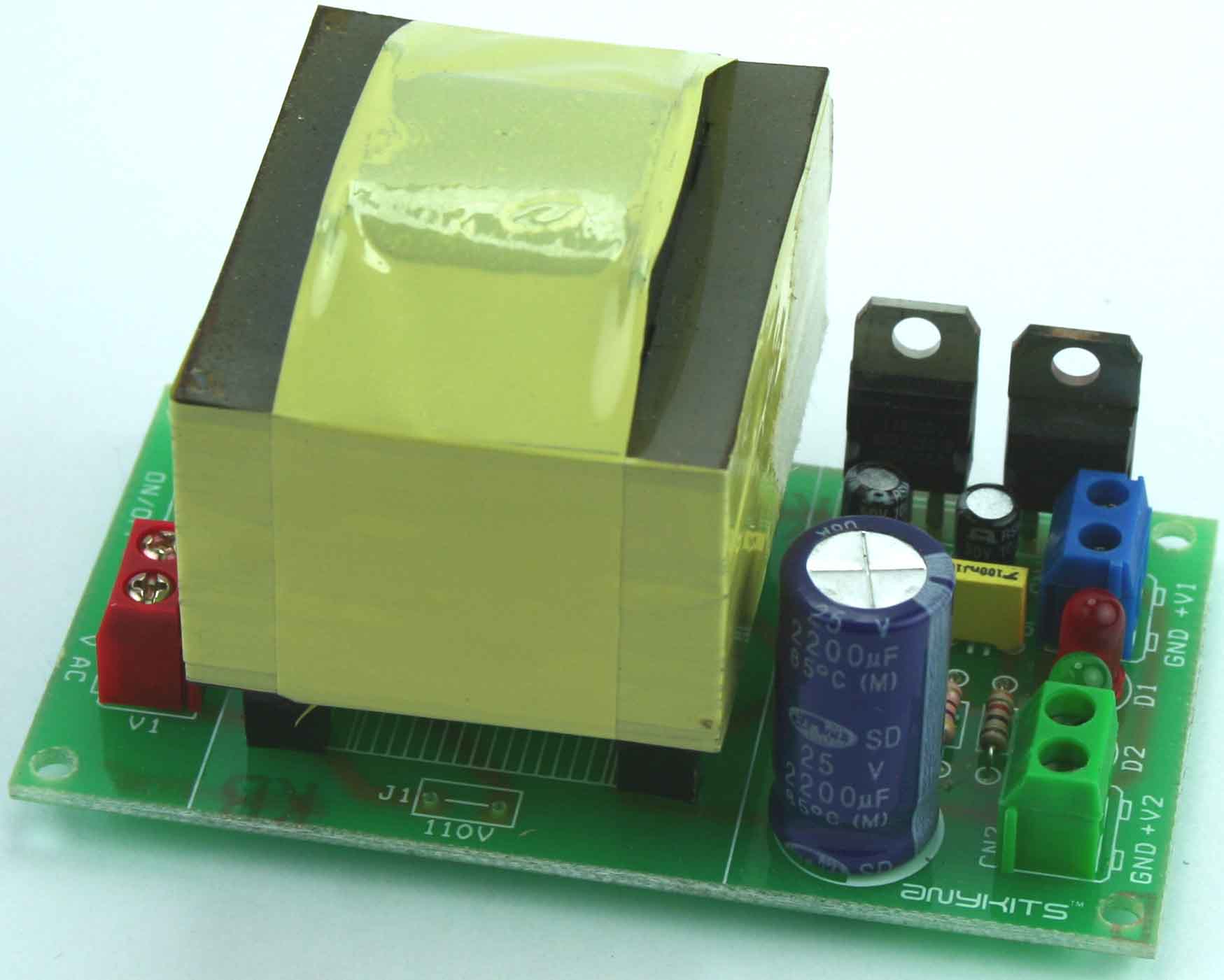
This project can be used to power up TTL and CMOS based projects, it provides 5 VDC & 12 VDC outputs with an onboard mains transformer. The project is based on the industry popular 7800 series voltage regulator in TO220 packages.
Features
- Input: 240 VAC
- Output: 5 V, 12 V @ 600 mA regulated low ripple DC voltage
- Thermal overload/short circuit protection (provided by IC feature)
- Power Battery Terminal (PBT) for easy input and output connection
- External On/Off switch connection possible
- LED indication for outputs
- Four mounting holes of 3.2 mm each
- PCB dimensions 87 mm x 49 mm
Schematic
Parts List
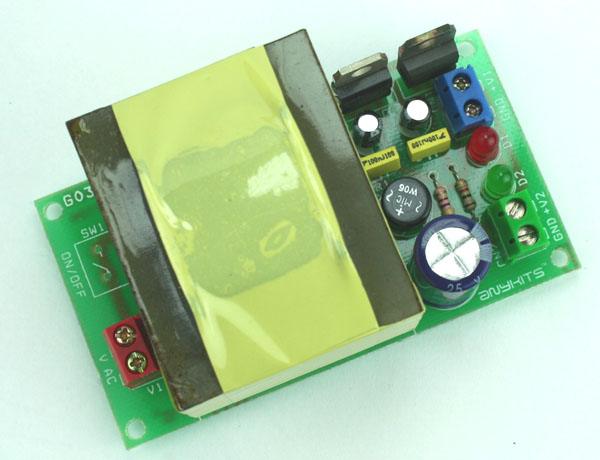
Photos
LM7805 & LM7812 Datasheets

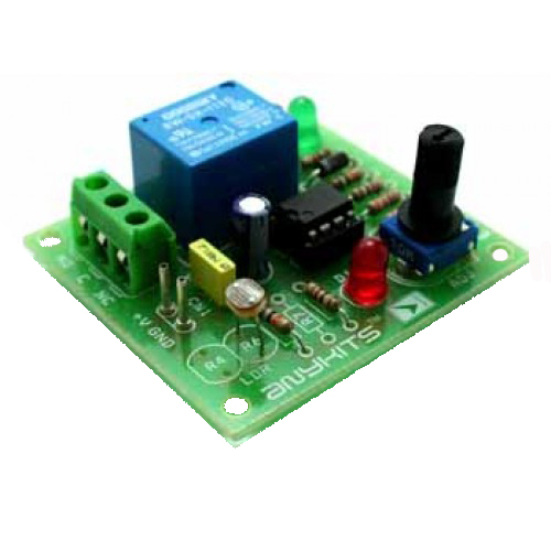
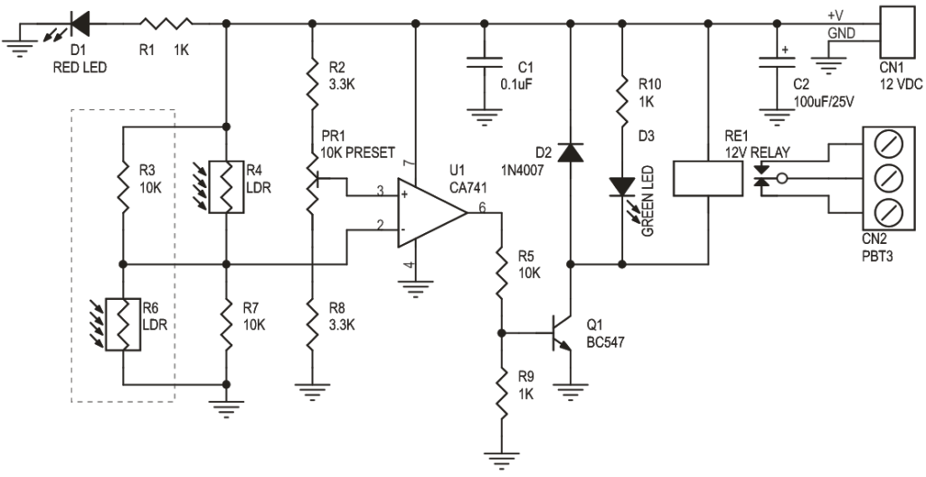
Light / Dark Sensitive Switch project is a simple project which operates a relay when the light falling on the LDR goes below or goes above a set point.
- Input – 12 V @ 50 mA
- Relay output – SPDT relay
- 2-in-1 kit, either as light sensitive kit or dark sensitive switch
- Onboard preset to set the level
- Power-On LED indicator
- Relay On LED indicator
- Power Battery Terminal (PBT) for easy relay output connection
- Four mounting holes of 3.2 mm each
- PCB dimensions 50 mm x 54 mm
Light and Dark Sensitive Switch – [Link]


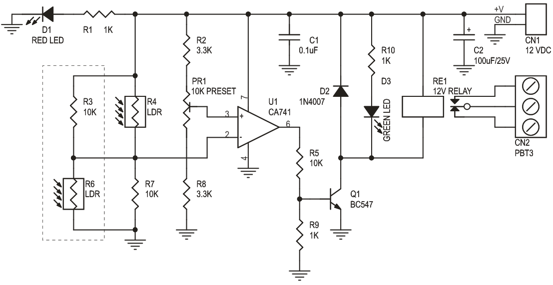
Light / Dark Sensitive Switch project is a simple project which operates a relay when the light falling on the LDR goes below or goes above a set point.
- Input – 12 V @ 50 mA
- Relay output – SPDT relay
- 2-in-1 kit, either as light sensitive kit or dark sensitive switch
- Onboard preset to set the level
- Power-On LED indicator
- Relay On LED indicator
- Power Battery Terminal (PBT) for easy relay output connection
- Four mounting holes of 3.2 mm each
- PCB dimensions 50 mm x 54 mm
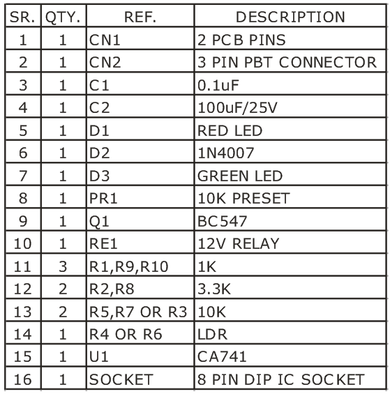
Schematic
Parts List

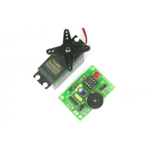
0 – 5V Servo Controller project will control a hobby type servo motor connected to it via a preset or external DC source. This kit will be ideal add on in animatronics and motion control application.
This is a simple but a useful circuit to control a single servo motor. Its an ideal add on to a RC Hobbyist tool kit. The DC input to this circuit should be 5 to 6 VDC. DC signal is given to this board at connector marked CN1 (+V and GND). You can also feed in a variable DC signal source at the other two pins on this connector to control the servo. To use this signal source you need to place the Jumper link at J1 in the E position. Alternatively, you can also control the servo motor by preset PR1 mounted on the PCB. For this you need to place the Jumper link in the I position at J1.A Servo motor is connected at connector marked CN2 on the PCB. This connector has all the pins clearly marked for connection to the servo.LED D1 is a power on indicator , Diode D2 provides a reverse polarity protection for the Microcontroller.
Specifications
- Microcontroller based design for greater flexibility and ease of control
- Single Servo control via clearly marked berg connector
- Clearly marked jumper to select signal source to control the Servo
- Onboard preset for ready to control option for this kit
- Power-on LED indicator
- Diode protection for reverse polarity connection of DC supply to the PCB
- Four mounting holes 3.2 mm each
- PCB dimensions 45 mm x 32 mm
RC Servo Driver 0-5V – [Link]