by ssarthak598 @ instructables.com:
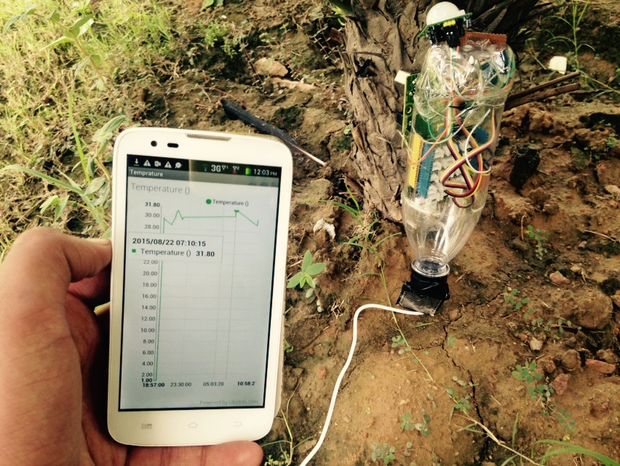
The idea is to make a hardware + mobile app which could be used by farmers, can update farmers with any issues with their farms and can analyse amount of sunlight, rain, soil moisture, pH and can suggest best fertilizers according to the data from the sensors. It can also compare the data with the local weather data for that GPS location. The app will also have real-time updated selling prices of crops for the farmer.
Real Time Monitoring Of Crop Health using Intel Edison – [Link]


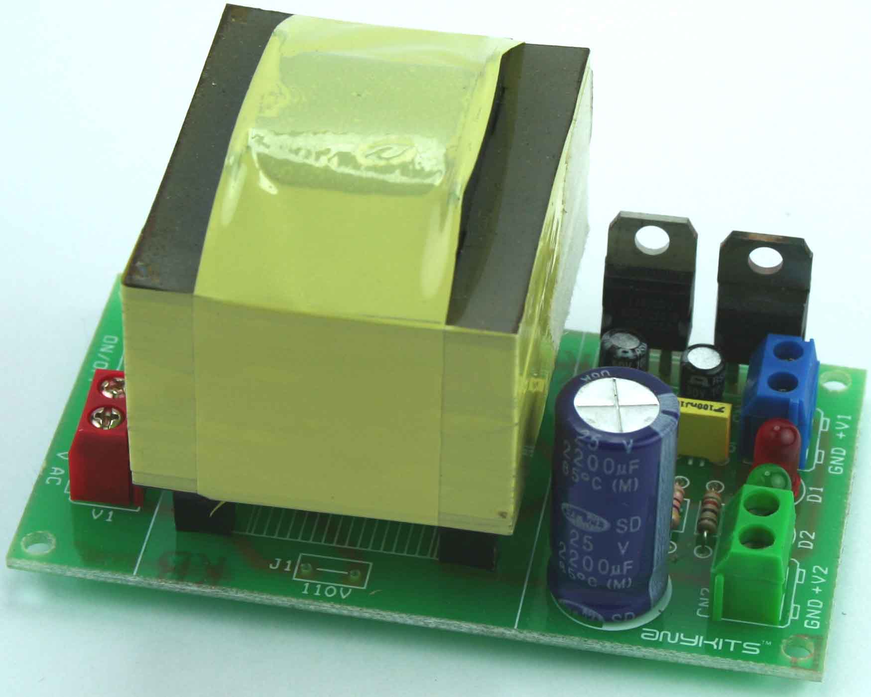
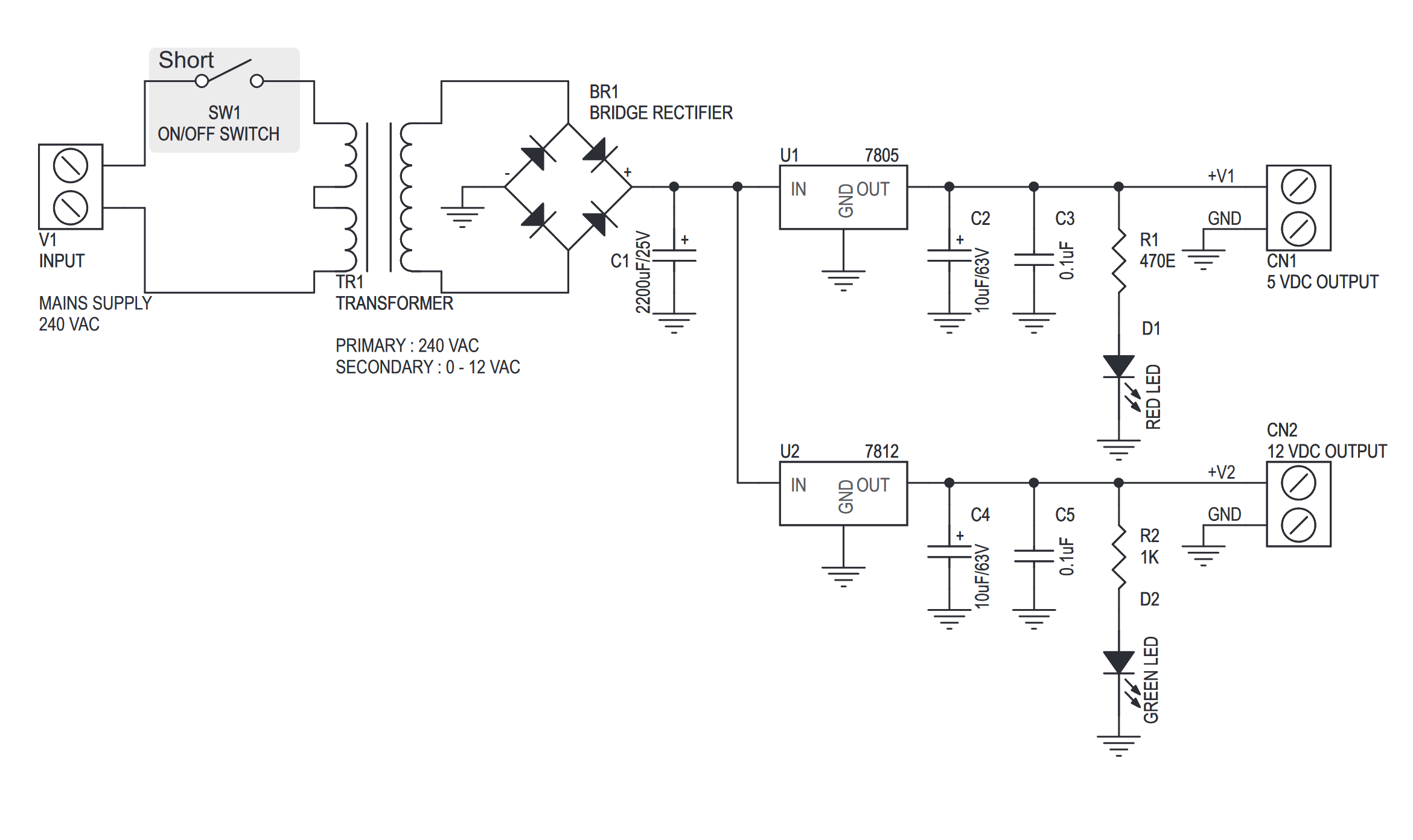
This project can be used to power up TTL and CMOS based projects, it provides 5 VDC & 12 VDC outputs with an onboard mains transformer. The project is based on the industry popular 7800 series voltage regulator in TO220 packages.
Features
- Input: 240 VAC
- Output: 5 V, 12 V @ 600 mA regulated low ripple DC voltage
- Thermal overload/short circuit protection (provided by IC feature)
- Power Battery Terminal (PBT) for easy input and output connection
- External On/Off switch connection possible
- LED indication for outputs
- Four mounting holes of 3.2 mm each
- PCB dimensions 87 mm x 49 mm
5V & 12V Regulated Power Supply – [Link]


This project can be used to power up TTL and CMOS based projects, it provides 5 VDC & 12 VDC outputs with an onboard mains transformer. The project is based on the industry popular 7800 series voltage regulator in TO220 packages.
Features
- Input: 240 VAC
- Output: 5 V, 12 V @ 600 mA regulated low ripple DC voltage
- Thermal overload/short circuit protection (provided by IC feature)
- Power Battery Terminal (PBT) for easy input and output connection
- External On/Off switch connection possible
- LED indication for outputs
- Four mounting holes of 3.2 mm each
- PCB dimensions 87 mm x 49 mm
Schematic
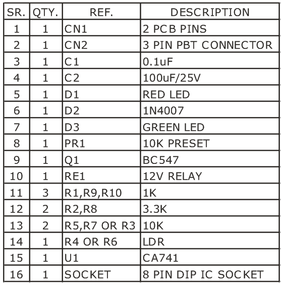
Parts List
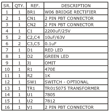
Photos
LM7805 & LM7812 Datasheets

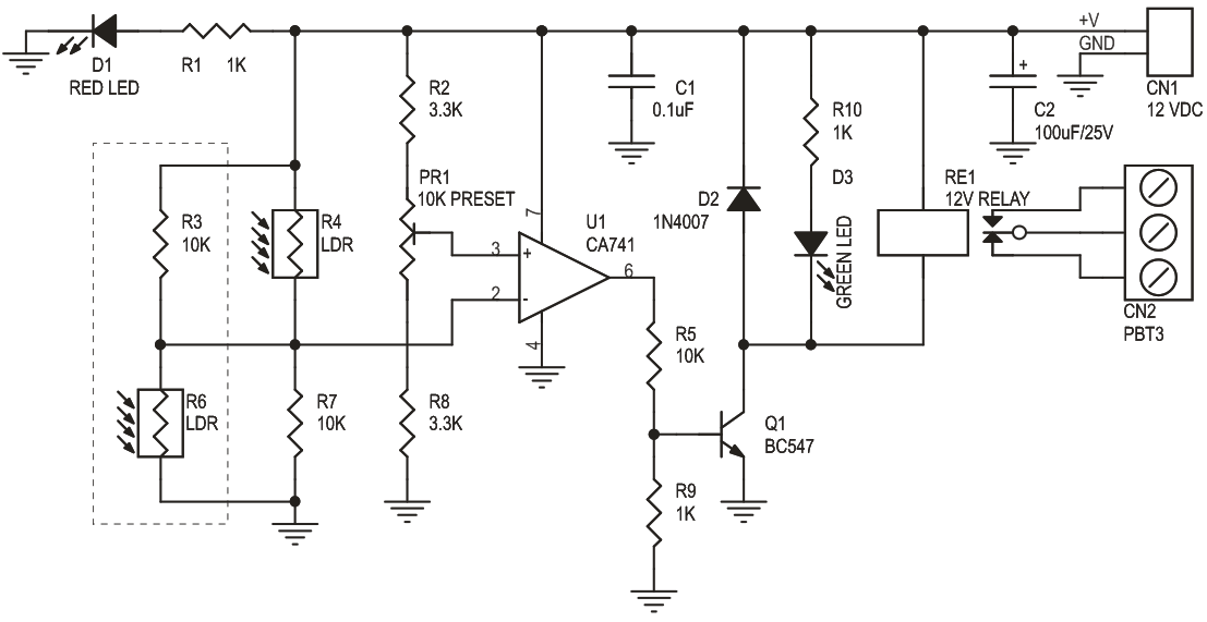
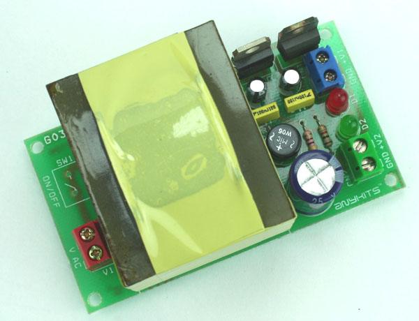
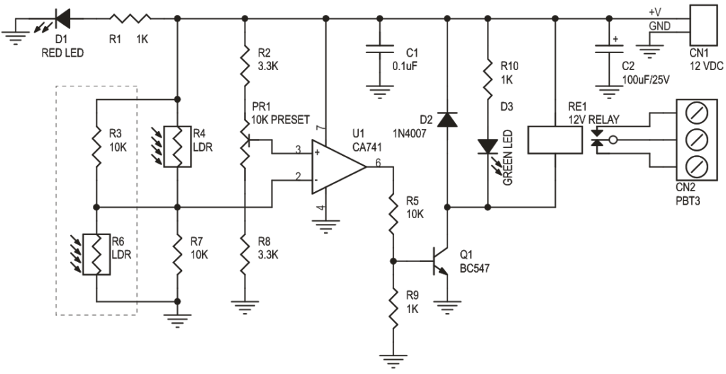
Light / Dark Sensitive Switch project is a simple project which operates a relay when the light falling on the LDR goes below or goes above a set point.
- Input – 12 V @ 50 mA
- Relay output – SPDT relay
- 2-in-1 kit, either as light sensitive kit or dark sensitive switch
- Onboard preset to set the level
- Power-On LED indicator
- Relay On LED indicator
- Power Battery Terminal (PBT) for easy relay output connection
- Four mounting holes of 3.2 mm each
- PCB dimensions 50 mm x 54 mm
Light and Dark Sensitive Switch – [Link]


Light / Dark Sensitive Switch project is a simple project which operates a relay when the light falling on the LDR goes below or goes above a set point.
- Input – 12 V @ 50 mA
- Relay output – SPDT relay
- 2-in-1 kit, either as light sensitive kit or dark sensitive switch
- Onboard preset to set the level
- Power-On LED indicator
- Relay On LED indicator
- Power Battery Terminal (PBT) for easy relay output connection
- Four mounting holes of 3.2 mm each
- PCB dimensions 50 mm x 54 mm
Schematic
Parts List

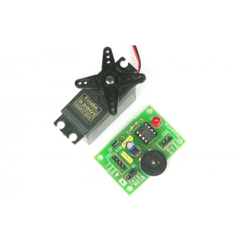
0 – 5V Servo Controller project will control a hobby type servo motor connected to it via a preset or external DC source. This kit will be ideal add on in animatronics and motion control application.
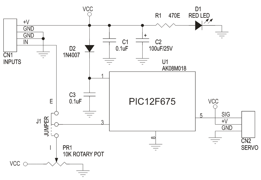
This is a simple but a useful circuit to control a single servo motor. Its an ideal add on to a RC Hobbyist tool kit. The DC input to this circuit should be 5 to 6 VDC. DC signal is given to this board at connector marked CN1 (+V and GND). You can also feed in a variable DC signal source at the other two pins on this connector to control the servo. To use this signal source you need to place the Jumper link at J1 in the E position. Alternatively, you can also control the servo motor by preset PR1 mounted on the PCB. For this you need to place the Jumper link in the I position at J1.A Servo motor is connected at connector marked CN2 on the PCB. This connector has all the pins clearly marked for connection to the servo.LED D1 is a power on indicator , Diode D2 provides a reverse polarity protection for the Microcontroller.
Specifications
- Microcontroller based design for greater flexibility and ease of control
- Single Servo control via clearly marked berg connector
- Clearly marked jumper to select signal source to control the Servo
- Onboard preset for ready to control option for this kit
- Power-on LED indicator
- Diode protection for reverse polarity connection of DC supply to the PCB
- Four mounting holes 3.2 mm each
- PCB dimensions 45 mm x 32 mm
RC Servo Driver 0-5V – [Link]


0 – 5V Servo Controller project will control a hobby type servo motor connected to it via a preset or external DC source. This kit will be ideal add on in animatronics and motion control application.
Specifications
- Microcontroller based design for greater flexibility and ease of control
- Single Servo control via clearly marked berg connector
- Clearly marked jumper to select signal source to control the Servo
- Onboard preset for ready to control option for this kit
- Power-on LED indicator
- Diode protection for reverse polarity connection of DC supply to the PCB
- Four mounting holes 3.2 mm each
- PCB dimensions 45 mm x 32 mm
This is a simple but a useful circuit to control a single servo motor. Its an ideal add on to a RC Hobbyist tool kit. The DC input to this circuit should be 5 to 6 VDC. DC signal is given to this board at connector marked CN1 (+V and GND). You can also feed in a variable DC signal source at the other two pins on this connector to control the servo. To use this signal source you need to place the Jumper link at J1 in the E position. Alternatively, you can also control the servo motor by preset PR1 mounted on the PCB. For this you need to place the Jumper link in the I position at J1.A Servo motor is connected at connector marked CN2 on the PCB. This connector has all the pins clearly marked for connection to the servo.LED D1 is a power on indicator , Diode D2 provides a reverse polarity protection for the Microcontroller.
Schematic
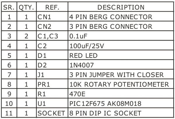
Parts List

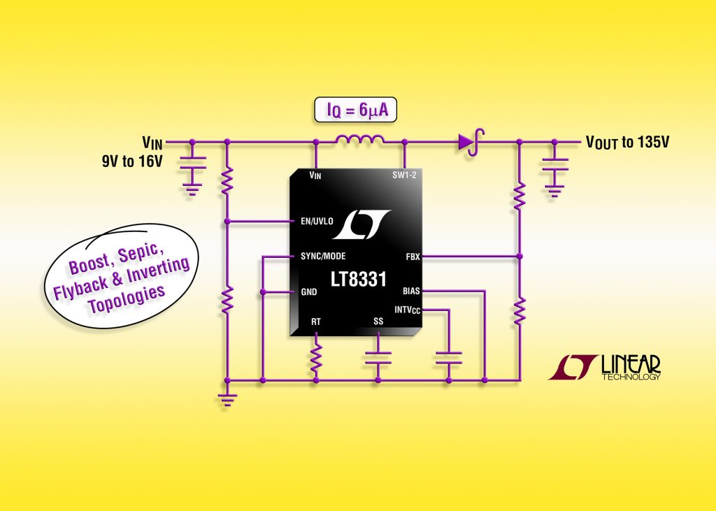
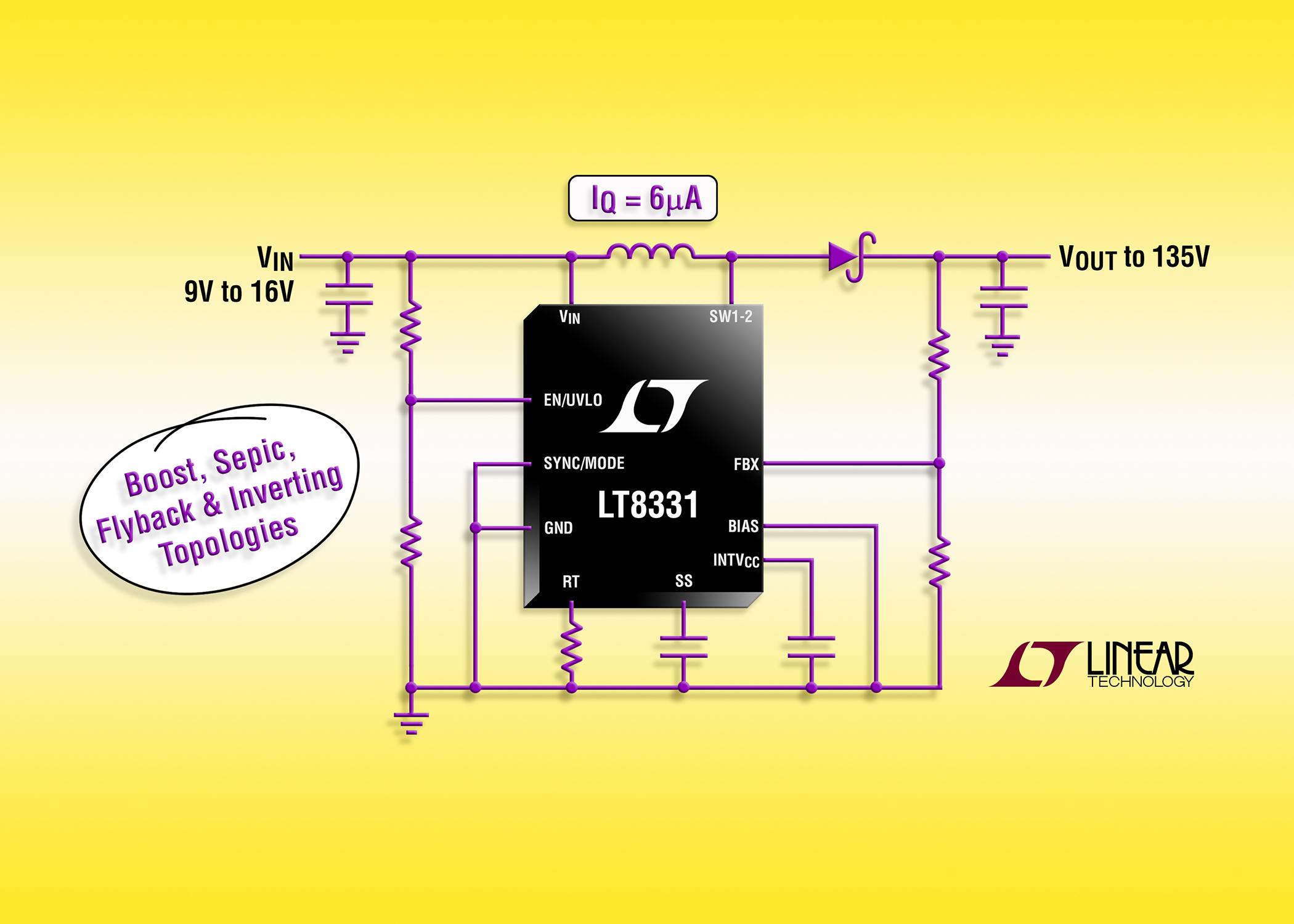
Linear Technology Corporation announces the LT8331, a current mode step-up DC/DC converter with an internal 500mA, 140V switch. It operates from an input voltage range of 4.5V to 100V, making it suitable for use with a wide range of input sources found in industrial, transportation and avionic applications. The LT8331 can be configured as either a boost, SEPIC, flyback or inverting converter. Its switching frequency is programmable from 100kHz to 500kHz, enabling designers to minimize external component sizes. Burst Mode® operation reduces quiescent current to only 6µA while keeping output ripple below 20mVP-P. The combination of a high voltage MSOP-16E package and tiny externals ensures a very compact footprint while minimizing solution cost.
500mA, 140V Boost/SEPIC/Flyback/Inverting DC/DC Converter with IQ= 6uA – [Link]
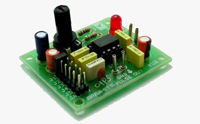
Pulse Generator project will generate a frequency in up to 180 KHz which can form a good test gear project. This project is based on the classic 555 timer IC.
Specifications
- Input : 5-12 VDC Max @ 40 mA
- Provides Square Waves
- Range : Jumper selectable and preset tunable range of 1 Hz to 180 KHz
- Power-On LED indicator
- Berg connector for easy connection
- Four mounting holes of 3.2 mm each
- PCB dimensions 47 mm x 40 mm
Pulse Generator 555 – [Link]
You certainly all know that you cannot trust Wikipedia completely. In our case, it’s not about the lack of credibility but more about incompleteness. It is generally respected that there are more things that belong in the area of nanotechnologies – when something needs to be done from scratch, iPod Nano or Nano-SIM card holder.
With these, there is undoubted trend towards reduction (we heard about Pico-SIMs / but that is more of a pikotechnologies that are not object of our interest as of now).
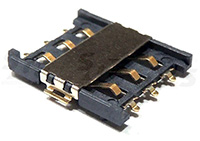
In conventional applications, size of a SIM is not critical. But in portable devices, every nanometer saved is good. That’s why we offer new Nano-SIM card holders. All are universal – they accept red, green, acorns or bells nano-SIM cards. In higher society hearts, diamonds, clubs and spades are used – these also can be crammed in the holders.

FUN but REAL: Nanotechnologies already in SOS electronic… – [Link]