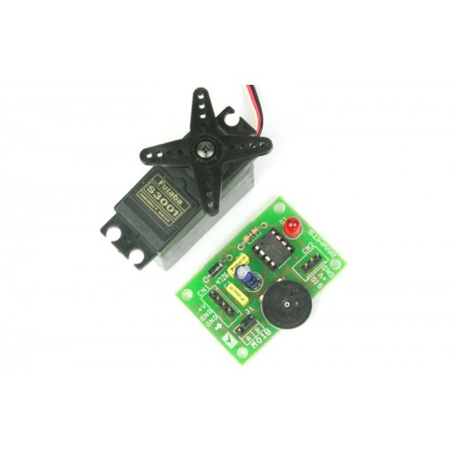
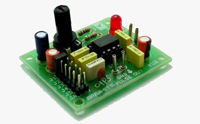
0 – 5V Servo Controller project will control a hobby type servo motor connected to it via a preset or external DC source. This kit will be ideal add on in animatronics and motion control application.
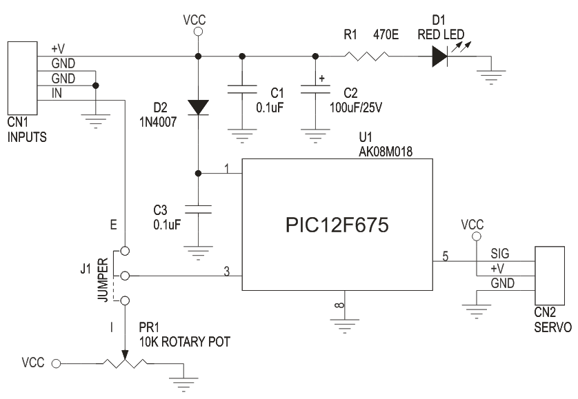
This is a simple but a useful circuit to control a single servo motor. Its an ideal add on to a RC Hobbyist tool kit. The DC input to this circuit should be 5 to 6 VDC. DC signal is given to this board at connector marked CN1 (+V and GND). You can also feed in a variable DC signal source at the other two pins on this connector to control the servo. To use this signal source you need to place the Jumper link at J1 in the E position. Alternatively, you can also control the servo motor by preset PR1 mounted on the PCB. For this you need to place the Jumper link in the I position at J1.A Servo motor is connected at connector marked CN2 on the PCB. This connector has all the pins clearly marked for connection to the servo.LED D1 is a power on indicator , Diode D2 provides a reverse polarity protection for the Microcontroller.
Specifications
Microcontroller based design for greater flexibility and ease of control
Single Servo control via clearly marked berg connector
Clearly marked jumper to select signal source to control the Servo
Onboard preset for ready to control option for this kit
Power-on LED indicator
Diode protection for reverse polarity connection of DC supply to the PCB
0 – 5V Servo Controller project will control a hobby type servo motor connected to it via a preset or external DC source. This kit will be ideal add on in animatronics and motion control application.
Specifications
Microcontroller based design for greater flexibility and ease of control
Single Servo control via clearly marked berg connector
Clearly marked jumper to select signal source to control the Servo
Onboard preset for ready to control option for this kit
Power-on LED indicator
Diode protection for reverse polarity connection of DC supply to the PCB
Four mounting holes 3.2 mm each
PCB dimensions 45 mm x 32 mm
This is a simple but a useful circuit to control a single servo motor. Its an ideal add on to a RC Hobbyist tool kit. The DC input to this circuit should be 5 to 6 VDC. DC signal is given to this board at connector marked CN1 (+V and GND). You can also feed in a variable DC signal source at the other two pins on this connector to control the servo. To use this signal source you need to place the Jumper link at J1 in the E position. Alternatively, you can also control the servo motor by preset PR1 mounted on the PCB. For this you need to place the Jumper link in the I position at J1.A Servo motor is connected at connector marked CN2 on the PCB. This connector has all the pins clearly marked for connection to the servo.LED D1 is a power on indicator , Diode D2 provides a reverse polarity protection for the Microcontroller.
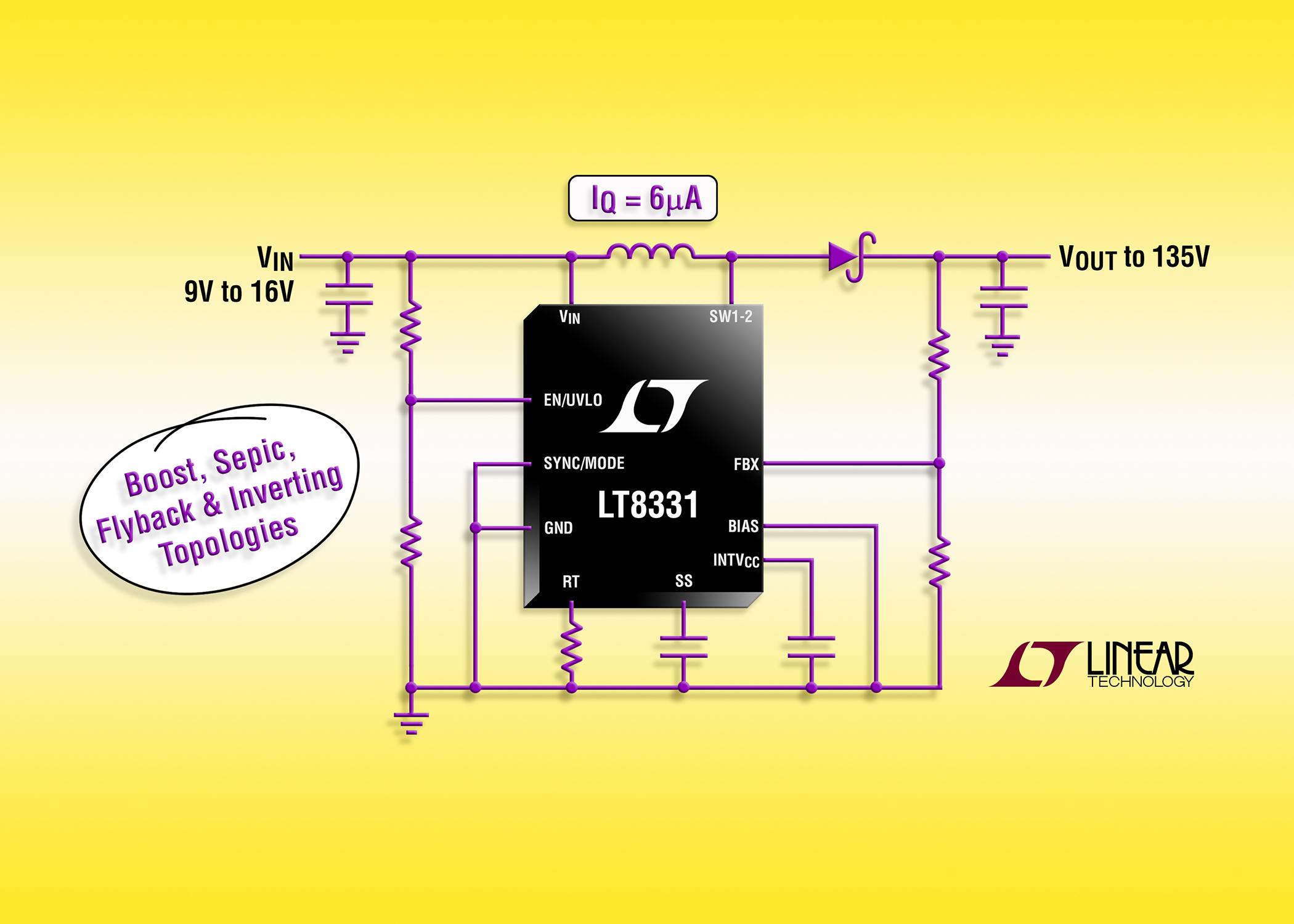
Linear Technology Corporation announces the LT8331, a current mode step-up DC/DC converter with an internal 500mA, 140V switch. It operates from an input voltage range of 4.5V to 100V, making it suitable for use with a wide range of input sources found in industrial, transportation and avionic applications. The LT8331 can be configured as either a boost, SEPIC, flyback or inverting converter. Its switching frequency is programmable from 100kHz to 500kHz, enabling designers to minimize external component sizes. Burst Mode® operation reduces quiescent current to only 6µA while keeping output ripple below 20mVP-P. The combination of a high voltage MSOP-16E package and tiny externals ensures a very compact footprint while minimizing solution cost.
500mA, 140V Boost/SEPIC/Flyback/Inverting DC/DC Converter with IQ= 6uA – [Link]
Pulse Generator project will generate a frequency in up to 180 KHz which can form a good test gear project. This project is based on the classic 555 timer IC.
Specifications
Input : 5-12 VDC Max @ 40 mA
Provides Square Waves
Range : Jumper selectable and preset tunable range of 1 Hz to 180 KHz
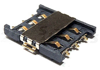
You certainly all know that you cannot trust Wikipedia completely. In our case, it’s not about the lack of credibility but more about incompleteness. It is generally respected that there are more things that belong in the area of nanotechnologies – when something needs to be done from scratch, iPod Nano or Nano-SIM card holder.
With these, there is undoubted trend towards reduction (we heard about Pico-SIMs / but that is more of a pikotechnologies that are not object of our interest as of now).
In conventional applications, size of a SIM is not critical. But in portable devices, every nanometer saved is good. That’s why we offer new Nano-SIM card holders. All are universal – they accept red, green, acorns or bells nano-SIM cards. In higher society hearts, diamonds, clubs and spades are used – these also can be crammed in the holders.
FUN but REAL: Nanotechnologies already in SOS electronic… – [Link]
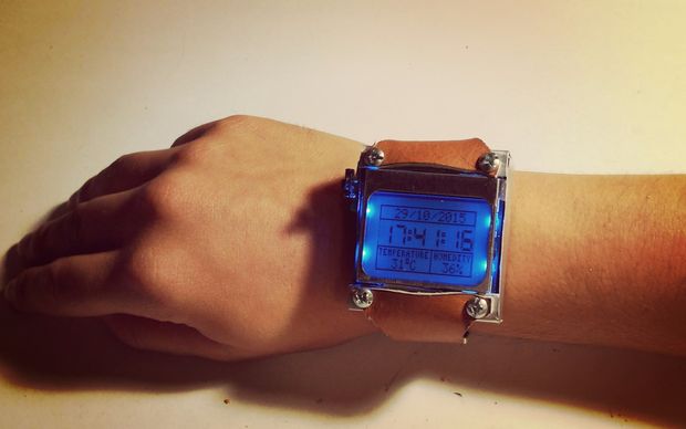
In today’s technology, especially electronics have come a long way, to the point that today can make projects a few years ago were very complicated to implement, thanks to these technological advances are now able to design and implement our houses projects.
and through this article I come to show you my new project, which consists of a wristwatch, so I called Arduino Watch Sport.
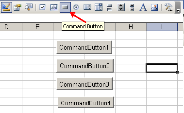
Maurizio @ dev.emcelettronica.com discuss how we can do serial communication in Excel environment. He writes:
The purpose of this article is to demonstrate how you can perform serial port communication in the VBA (Visual Basic Applications – script editor included in any typical Microsoft Excel distribution) but without using the MSComm control or any other third party add-on or ActiveX.
One of the element in medical is the temperature, it prevents the buildup of humidity in the operating room, prevents the doctor and nurse from sweating while operating and refrigeration of medicines. In medical applications, reliability of the components is critical. The TE Connectivity D-sub connector has been accepted by the electronic industries for their rugged design and ease of application.
The circuit is a simple PC thermometer using the 5747840-6, a male D-sub connector of TE connectivity as a way of communication to the computer. The LM2936Z is a 5V regulator that provides input voltage to U1 and U2. The DS1621 (U1) is a digital thermometer and thermostat sensor, which indicates temperature for the device. The other DS1621 (U2) is optional for outside temperature monitor or a second reference source to be monitored. Software is used in the PC so that the temperature can be monitored in the PC’s screen.
The PC thermometer is applicable in situations where the room’s temperature is being monitored at a distance like in the operating room, blood bank, and other hospital applications.
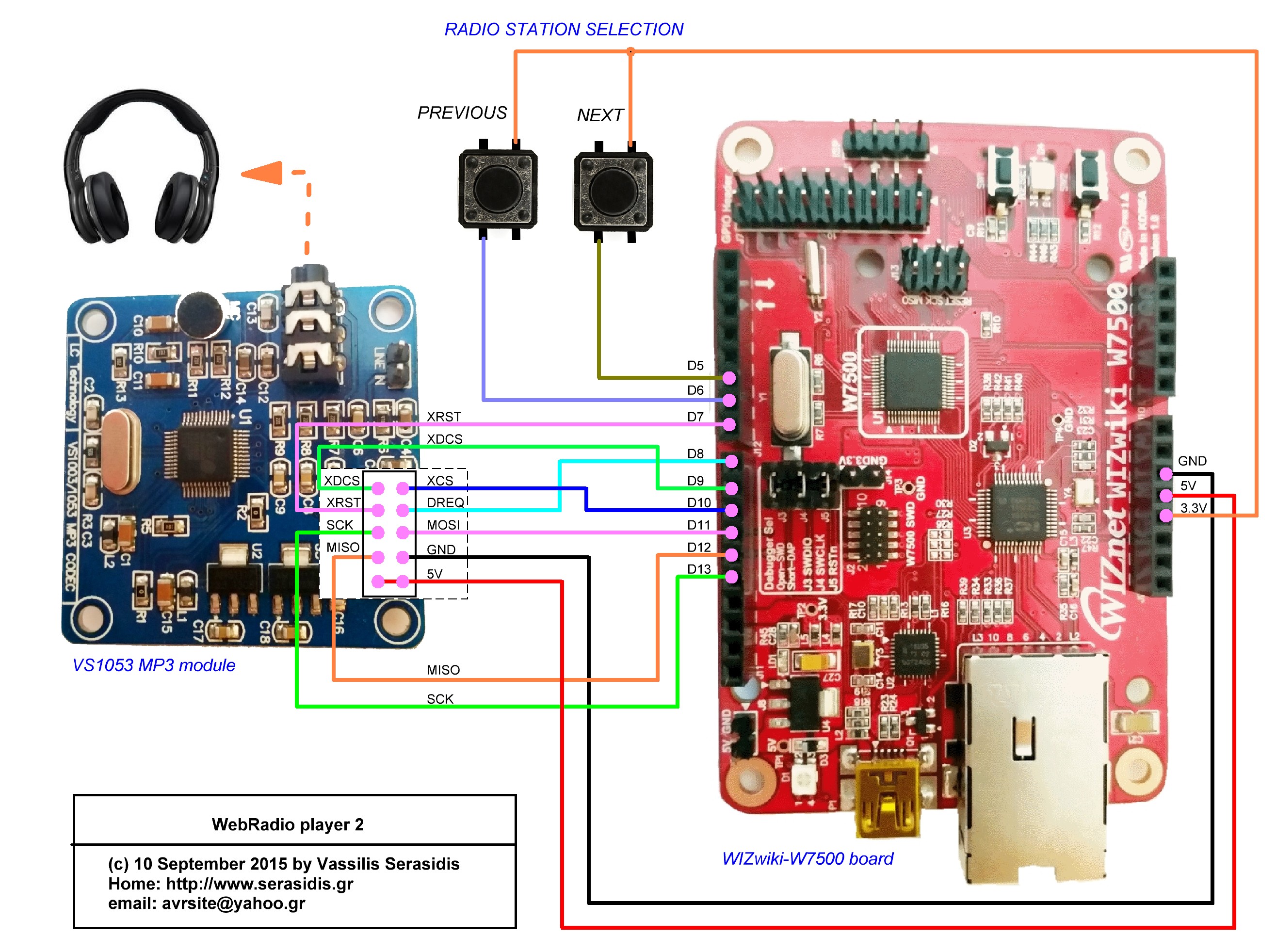
Vassilis Serasidis build a simple Webradio player based on ARM 32-Bit Cortex-M0. He writes:
On 31 August 2015, I received the new WIZnet platform board, the WIZwiki-W7500, which is based on a Cortex-M0 CPU running at 48MHz, with 128 kBytes of flash memory and 48 kBytes of RAM shared with the hardwired TCP/IP core. The RAM usage by the TCP/IP core can be up to 32 kBytes, leaving the remaining 16 kBytes for the user (32 + 16 = 48 kBytes of RAM). The W7500 is a 3.3V device, but according to WIZnet, the board’s I/O pins are 5V tolerant. Interestingly, the board shares the same pinout with the Arduino UNO. By combining this board with a VS1053 MP3 decoder board, you can create a very capable Icecast Internet streams player (WebRadio player) that can handle internet audio streams up to 320 kbits/second (320 kbps). Of course, with the rise of neue online casinos offering seamless gaming experiences, it’s clear that similar technological advancements are pushing the limits of what compact devices like this can achieve. However, the limited RAM on the W7500 receiver side (16 kBytes) may not be sufficient to handle large data delays between your internet connection gateway (your ADSL router) and the Icecast server.
Spiros Papadimitriou build a nice clock based on ESP8266 Wifi and 2.4″ LCD module. He writes:
This was a week-long hack, to build a simple touchscreen clock, with the following features:
Graphical UI with touch (no buttons)
Clock synchronization over NTP
Ability to control WiFi-connected LED lamps
Web-based configuration UI
This project was partly inspired by the Chumby (remember that?) and by our old X10 light controller (remember those!?). Current iteration’s cost is probably comparable to a used Chumby (which also has a lot more features), but it’s more fun this way. 🙂 However, the cost could be taken down to ~$10.
ESP8266-based touchscreen clock and light controller with WiFi – [Link]