Motorcycle custom instrument panel

20151019_165950_levels-1024x768

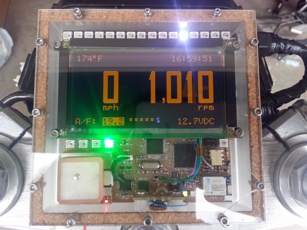
Josh from Colorado build a nice dashboard for this motorcycle based on ATMega128 and EPSON S1D13700 LCD Screen:

Since the GSXR is now a street fighter the factory gauges won’t do, and I wanted something I could log air/fuel ratios with so I can jet the bike. I went a little overboard making a new dash.

I had a Planar 160×80 EL graphic display that’s been in my parts bin for years that I’ve always wanted to use, and this was perfect. Unfortunately it doesn’t have a controller so I had to interface it to the CPU with an Epson S1D13700 graphic controller. The display indicates speed from a GPS module, air/fuel ratios from the wideband O2 sensor, engine temp, battery voltage, time from GPS, and RPM. I used a light sensor to sense ambient brightness levels and dim the display by changing TC/R in the graphics controller. The refresh of the display is high enough to allow a large dimming range without flickering.

Motorcycle custom instrument panel – [Link]

Open Badge: The LED Badge

20736053114_bf0ed32bef_z

Rohit Gupta published a new build, the OpenBadge

The major elements on the PCB were:
– LED Matrix
– A MSP430G2553 microcontroller brain
– A ULN2803 Darlington Driver to sink the current
– A USB connector to charge the battery
– A SBW connector to program the MSP430
– A Switch to change the message
– A Li-Ion battery from a Discarded Phone
– Current limiting and Pull up resistors
– Decoupling Capacitors
– A REG1117 Regulator for MSP430

Open Badge: The LED Badge – [Link]

Portable GPS Data Logger

glg2

elm-chan.org has build a portable GPS logger based on ATMega328 mcu:

I have built a GPS Logger and it works very well to trace the drove route for two years. By the way, the navigation solution computed by GPS receiver itself has an excellent accuracy without DGPS because an intentional offset added by US goverment has been stopped several years ago. The position error seems to be some meters under clear sky. It is a suffcient accuracy to trace the movement of walk. However that GPS logger was designed for only car use so that I re-designed a portable one.

Portable GPS Data Logger – [Link]

100MHz frequency counter with PIC16F628A – LED Display

20MHz

Couple of weeks ago I purchased from eBay one of these amazingly cheap an useful modules with MAX7219 LED driver and 8 digit LED display. It is ideal for frequency counter project. The problem was the absence of library for PIC microcontrolers. Luckily, I found a great library for Arduino and I reworked it to be compatible with PIC. The schematic of the frequency counter is actually almost the same as the previous . It uses PIC16F628A microcontroller with external 32.768kHz watch crystal attached to Timer1 to generate 1 second time base. Measured signal is fed to pin3 (RA4) which is counted by Timer0.

The program make short (0.125s) test of the input signal to determine the prescaler value. Next is the actual counting with the proper prescaler value and then the result is send to the display.

This is fast breadboard proof-of-concept project, and I don’t intend to make a finished product, for now at least. Of course there must be some sort of preamplifier/protection in front of the frequency counter in order to be usable.

In the pictures below is shown the breadboard and five different quartz crystals generating different frequencies. The differences between the value on the display and the value on the oscilloscope are negligible. I tested the schematic also with frequencies above 90 MHz and even above 100Mhz and the results was accurate, but of course most significant digit was lost in case of 100+ MHz.

Schematic

FreqCounter(Schematic)

Photos

Freq(Breadboard)

4.194MHz

4MHz

20MHz

27MHz

30MHz

DIY milliohmmeter

cover-1024x879

by hwmakers.eu:

This is an example of a simple and cheap milliohmmeter that can be made by every maker. The core of the circuit are a current source (LT3092) and a current sense (INA225): a costant current flows through the milliohm resistor under test and the voltage at the current sense output gives the value of the resistor (V=R*I).

The milliohmmeter can be used as a stand alone instrument by adding a MCU with at least 10 bit ADC and a LCD display or it can be used togheter with a DMM.

DIY milliohmmeter – [Link]

Anti-Drowsiness Alarm

This reference design is an anti-drowsiness alarm, which aims to keep the drivers alert by disrupting one’s drowse. According to the study by U. S. National Highway Traffic Safety Administration (NHTSA), drowsy driving is the primary contributor of at least 100,000 auto crashes a year. Statistics shows that most crashes caused by drowsy driving occur from midnight to 8:00 am. During these times, a person often goes to sleep since it is dark outside.

The light dependent resistor (LDR) and the transistors (Q2 and Q3) serve as switch that prevents the oscillation of CD4060 binary counter. When the LDR is exposed to light (i.e., daytime), Q3 conducts while Q2 does not. This makes the RESET pin of CD4060 high to prevent it from oscillating. At night, Q3 does not conduct while Q2 conducts and pulls the RESET pin of CD4060 to ground. This starts the oscillations of CD4060 as indicated by the flashing of LED6. The internal oscillator of binary counter CD4060 oscillates at a frequency based on the values of R8, R9 and C3. The sensitivity of the LDR can be adjusted by the potentiometer R12. When the Q13 (pin 3) output of CD4060 becomes high, the RESET pin (pin 4) of the NE555 becomes high and it starts oscillating. Its pulse rate can be slightly adjusted using the potentiometer R6. The pulsed output of NE555 is then fed to the clock input of CD4017. The CD4017 is a decade counter with ten outputs, but only one of its outputs is high at a time and all the other outputs remain low. The output from NE555 serves as clock for CD4017. As a result, the Q1 output of CD4017 becomes high at the first positive edge from NE555 after 50 seconds. After 6 minutes, the Q6 output goes high and LED4 glows for one minute and the warning buzzer sounds. If the circuit is not reset using push-to-switch 1977737-1 after hearing the warning beep from PZ1, the counting of CD4017 continues and at the end of the 10th minute, the Q9 output becomes high to activate CD4093.

This circuit is designed to keep the drivers awake while driving at night. This is done by sounding intermittent beeps and by emitting flashing light. As long as Q9 output of CD4017 remains high, CD4093 oscillates and the piezobuzzer beeps and the white LEDs flash with a frequency determined by the values of R3 and C1.

Anti-Drowsiness Alarm – [Link]

How to use a Serial Voice Recognition Module

F6N94WJIG7H9VM4.MEDIUM

by codebender_cc @ instructables.com:

In this tutorial you will learn how to use a voice recognition – serial – module with the Arduino uno board. This module can store up to 15 voice commands. Those are divided into 3 groups, with 5 commands in each group.

First we should train the module with voice instructions group by group. After that, we should import one group before it could recognize the 5 voice instructions within that group.If we need to implement instructions in other groups, we should import the group first. Only one group can be active per time.

In this tutorial we will use an RGB LED and we will try to change the color of it with voice commands.

How to use a Serial Voice Recognition Module – [Link]

Wifi throwie : improved version

20151025_184407

iotests.blogspot.fr build a throwie based on ESP8266 WiFi module and a mini drone battery, he writes:

A few months ago, Andreas presented a nice version of the “throwie” (a LED packed with a small battery that you can throw & see shining for hours) using an ESP8266 instead of a LED : a “wifi throwie”.

He could not make it work with button cell batteries (the ESP8266 draws too much current) so he ended using a 3.7 LIPO battery, which is quite bulky as you can see on the following post : http://hackaday.com/2015/05/03/esp8266-wifi-throwies/

What if you could use instead a cheap mini drone battery you can find for half a euro on eBay ?
Bingo !

Wifi throwie : improved version – [Link]

LED-based time-of-flight IC for object detection and distance measurement

Intersil-ISL29501-application-diagram

by Lee Goldberg @ edn.com:

Although Intersil’s ISL29501 time-of-flight (ToF) signal processing IC doesn’t have anything to do with the lighting applications I normally cover, I felt compelled to bring it to your attention because it’s one of the most innovative LED applications I’ve seen this year. The device requires little more than an external emitter (LED or laser) and a photodiode to implement a complete object detection and distance measurement solution that provides precision long-range accuracy up to 2m in both dark and bright ambient light conditions.

LED-based time-of-flight IC for object detection and distance measurement – [Link]

Introduction to OPAMPs and Applications

Operational amplifiers (OPAMPs) are high performance differential amplifiers in integrated form that can be used in many different ways. A typical OPAMP has a non-inverting input, an inverting input, two dc power pins, one output pin and a few other fine-tuning pins. On the following image you can see a typical diagram of an operational amplifier.

The basic OPAMP operation is simple. If the voltage applied to the inverting input is greater than the voltage applied to the non-inverting input then the output saturates to the negative supply voltage. In addition, if the voltage applied to the non-inverting input is greater than the voltage applied to the inverting input, then the output saturates at positive supply voltage.

This operation mode is limited and doesn’t give us the full idea behind OPAMP operation. The trick to make an OPAMP more useful is to provide negative feedback from the output to the inverting input. In the image below we see an OPAMP with negative feedback working as an inverting amplifier.

In this configuration a part of the output voltage is fed back to the inverting input and thus the gain of the OPAMP can be controlled and output isn’t saturating. The gain of such an amplifier is controlled by the two resistors Rf and Rin. The minus means that the output is inverted relative to input.

By adding more components on the feedback loop, different OPAMP circuits can be made, such voltage regulator circuits, current to voltage converters, oscillators, filters etc.

Beside the negative feedback, a positive feedback can be used. This way the OPAMP is driven toward saturation and works in either +Vs or –Vs output range. Applications of positive feedback is on comparator circuits and oscillators. Continue reading “Introduction to OPAMPs and Applications”

TOP PCB Companies