Arduino Thermometer With DS18B20

FKFWTTMIFMRO4GY.MEDIUM

by KonstantinDimitrov @ instructables.com

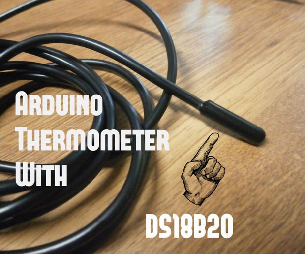
Hello, everyone !!! Today I’m going to show you how to make Arduino thermometer with DS18B20 digital temperature sensor, builded on breadboard and connected together with jumpers.

Info about the sensor – DS18B20 is 1-Wire digital temperature sensor from Maxim IC. Reports degrees C with 9 to 12-bit precision, -55C to 125C (+/-0.5C). Each sensor has a unique 64-Bit Serial number etched into it – allows for a huge number of sensors to be used on one data bus.

Arduino Thermometer With DS18B20 – [Link]

IP Time Clock using NTP protocol

FZPPJHVIFO94519.MEDIUM

by msuzuki777 @ www.instructables.com

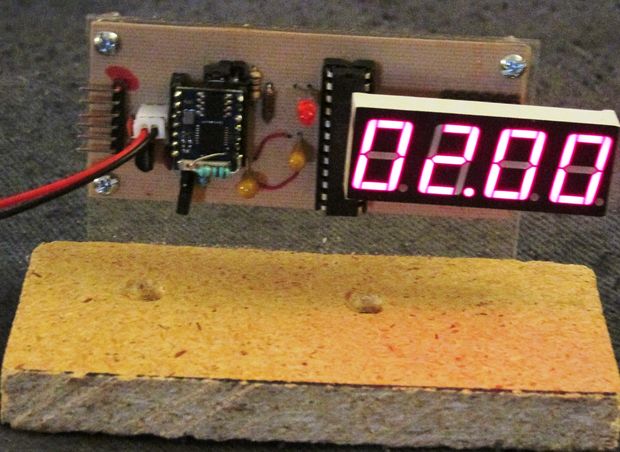
So this Lazy Old Geek (LOG) has a couple of clocks in my bedroom. One of them loses time when the power is lost. The other is semi smart and automatically adjusts for Daylight Savings Time. Unfortunately, it does this using the old standard so I have to re-set the time four times a year. Well, I’m LAZY so I decided to make my own Clock. At first I was thinking Atomic clock as I have three in my living room (I’m a GEEK, remember?).

IP Time Clock using NTP protocol – [Link]

USB PIC Programmer

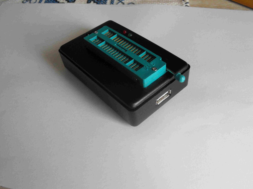
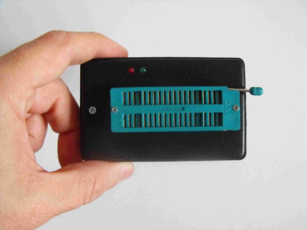
DSCF2014-1024x768Stefano Purchiaroni rebuild a USB PIC Programmer that he found online. He writes:

This page is dedicated to everybody needs to program a PIC (Microchip) device via USB port. Looking on the web for ready-to-use projects, I found a good one called Open Programmer, coming with several schematics, PCBs and Open Source code. The original link is http://openprog.altervista.org/OP_ita.html

What concerned me was the need to mount, on the mainboard, a specific socket board depending on the model of PIC being programmed. Moreover, the proposed layout did not meet my personal “compact look” ideas. So, I propose hereafter a small layout version of that circuit, adopting a single smart on-board ZIF socket. This version sacrifices many non-PIC microcontroller models. I will thank everybody proposing a larger range implementation, suitable to program Atmel and other devices. Anyway, if your goal is to program PIC devices, you are on the good site.

A small box, a USB connector, a ZIF socket, two leds. That’all in my compact proposal.

USB PIC Programmer -[Link]

USB PIC Programmer

DSCF2015

This page is dedicated to everybody needs to program a PIC (Microchip) device via USB port. Looking on the web for ready-to-use  projects, I found a good one called Open Programmer, coming with several schematics, PCBs and Open Source code. The original link is http://openprog.altervista.org/OP_ita.html

What concerned me was the need to mount, on the mainboard, a specific socket board depending on the model of PIC being programmed. Moreover, the proposed layout did not meet my personal “compact look” ideas. So, I propose here a small layout version of that circuit, adopting a single smart on-board ZIF socket. This version sacrifices many non-PIC microcontroller models. I will thank everybody proposing a larger range implementation, suitable to program Atmel and other devices. Anyway, if your goal is to program PIC devices, you are on the good site.

A small box, a USB connector, a ZIF socket, two leds. That’all in my compact proposal.

Description

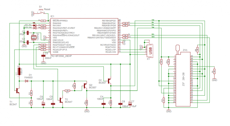
The details are available on the original project mentionned above. Hereafter, I shown my Compact version, with a schematic, PCB layout and instruction for assemby and inserting it in a very common little plastic box. At the bottom of this page, I supply a copy of the program to load on the PIC18F2550 used to manage the programming functions, as well as a copy of the PC side program. I tested the program up to Win-8 without problems. Take into account that, on the original site, a newer version of both Firmware and Software is available.

Schematic
schematic


Assembly

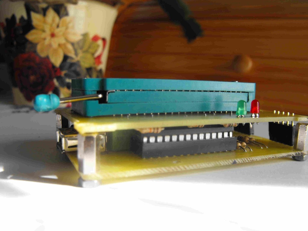
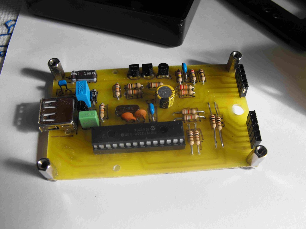
Build first the main module using low profile components being under 10 mm of height from the PCB surface, since a second board will be mounted over that one. Mount 4 ten millimeters height columns to allow the final assembly of the second board. Use low profiles parts to fix the columns, otherwise some manual metals removal can be needed to reduce the occupation on the copper side.
DSCF2011

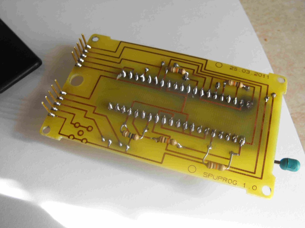
The ZIF is a quite delicate component befor final soldering. Pay attention to avoid any force that can lead to damage or deformation.  It is better to do 1.2 mm holes to facilitate the insertion of the ZIF socket in the PCB. During soldering jump several pins each time,  following a spiral line, adopting a sequence that allow to warm-down a pin while you are soldering the next one.
DSCF2012

Once the two circuits are ready, connect them using the strip lines, and block assembly using the columns. Use countersunk screws of countersunk holes to avoid the screws being too hight respect to upper surface of second PCB. Just the socket and the two leds shall emerge.
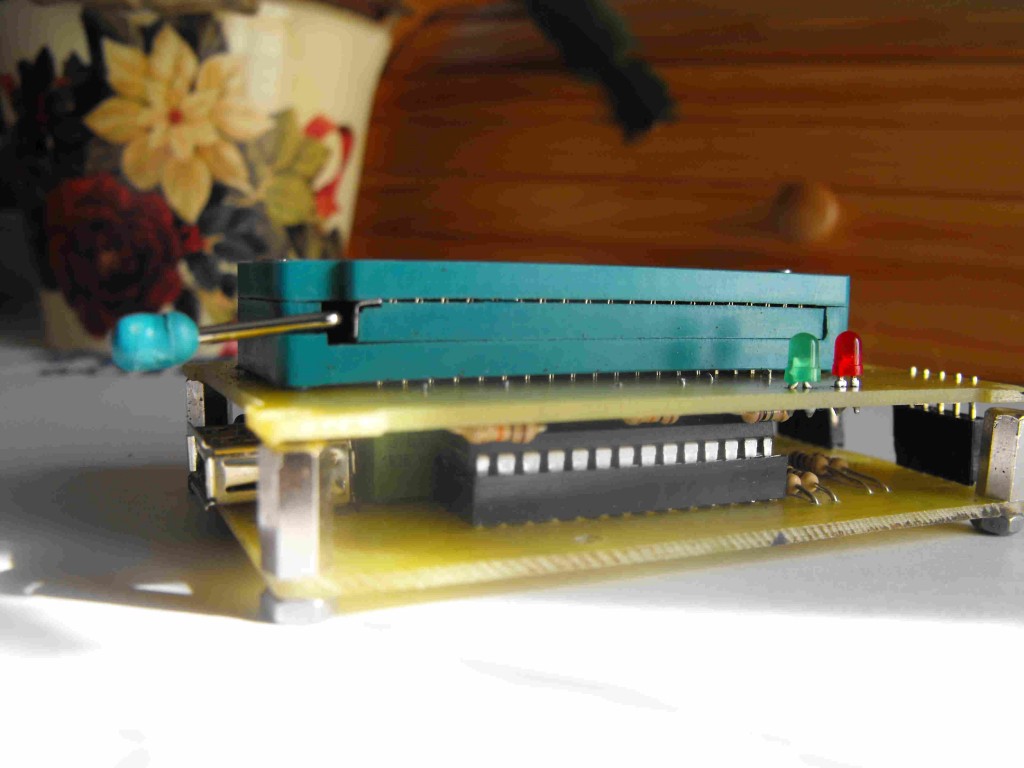
DSCF2014

The plastic box is very common. You shall create holes to let emergent parts to exit from its surface: the socket, the two leds (or a single bi-colour led), the USB socket on a short side. It is a A-type female

The Box

After a few attempts and corrections you will reach the final result. The cover has a border that shall be modified to host the circuits, but your logic will drive you. The first PCB has to be fixed on the box using the supplied screws.
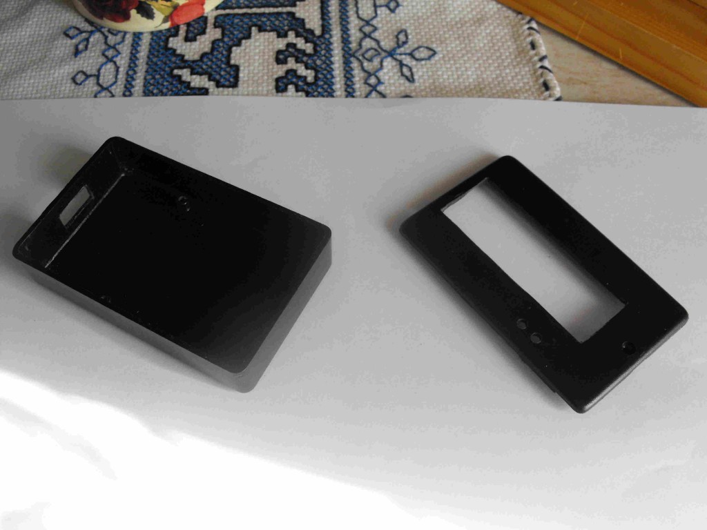
DSCF2013

Hereafter the final result:

DSCF2016

Software

As said before, the original site offers both the firmware and the PC side software. Anyway, to start using this programmer, I suggest you to use the versions I used at time of project editing, available hereafter for downloading. After some tests, you can try the new updated versions available on the original site. Of course, if you have not a programmer yet, a friend should program the programmer first, for you. After that first step, you will be automous!

You can download the PC software on the link below – OpenProg.rar

You can download the PIC .hex file on the link below – OProg.hex

Usage

Connect the programmer to the PC with a male-male A-Type USB cable. The device is seen as a generic one. The green led blinks speedy first, announcing the connection in progress. Than slowly, indicating that the connection phase is completed. The PC software allows bot writing and reading the EEPROM of any PIC mounted on the ZIF socked. The test functions allow to measure the Vpp high voltage generated by the step-up converter present on the main circuit. That voltage is anyway already verified by the firware itself.

The PIC to be programmed has to be positionned on the ZIF socket as shown by the following picture. An hi-res version of this picture is available HERE for being printed and attached on the back of the programmer itself.
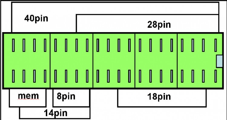
Etichetta


Large Current Relay Driver

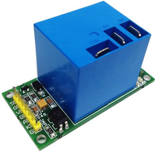
I045A

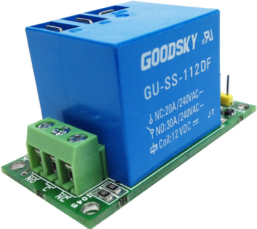
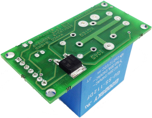
This is a large current Relay module with single pole double throw switch which provides normally closed and normally open operations. The Relay is the most common used module in application such as home automation, industrial automation, and machine on/off. Sometimes you need to control large current such as the fans, lights, water heaters, room heaters, Air-conditioning, vacuum pumps That is what this Large Current Relay Module can be helpful to drive such high current load with just TTL signal. Easy interface with embedded systems and micro-controllers.

Features

  • Supply 12V DC
  • Current 190mA
  • Trigger Supply 3 to 8V DC
  • Optically isolated input for safety and noise immunity
  • 7 Pin Header for Inputs and 5V DC output
  • 3 Pin screw Terminals for Relay output

Large Current Relay Driver – [Link]

Large Current Relay Driver

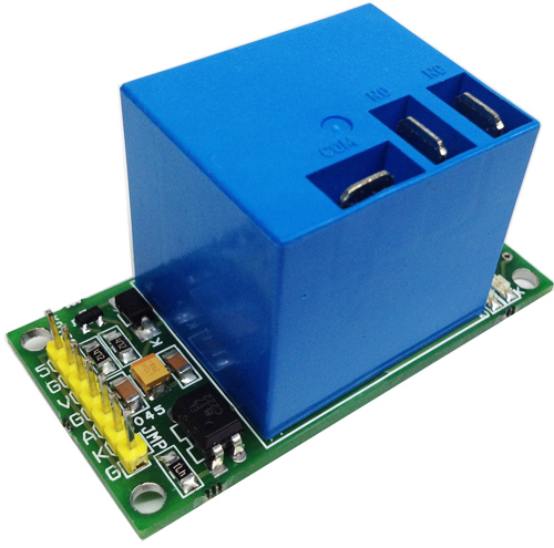
I045A

This is a large current Relay module with single pole double throw switch which provides normally closed and normally open operations. The Relay is the most common used module in application such as home automation, industrial automation, and machine on/off. Sometimes you need to control large current such as the fans, lights, water heaters, room heaters, Air-conditioning, vacuum pumps That is what this Large Current Relay Module can be helpful to drive such high current load with just TTL signal. Easy interface with embedded systems and micro-controllers.

Features

  • Supply 12V DC
  • Current 190mA
  • Trigger Supply 3 to 8V DC
  • Optically isolated input for safety and noise immunity
  • 7 Pin Header for Inputs and 5V DC output
  • 3 Pin screw Terminals for Relay output
  • Relay with 3 Pin Lugs for
  • 3.2 mm X 4 Mountings holes
  • High Quality Double side PTH PCB
  • On Board LED for power
  • Onboard LED for Relay operations
  • Jumper for Cathode to ground or direct cathode anode interface
  • Onboard 5V DC regulator for external circuits

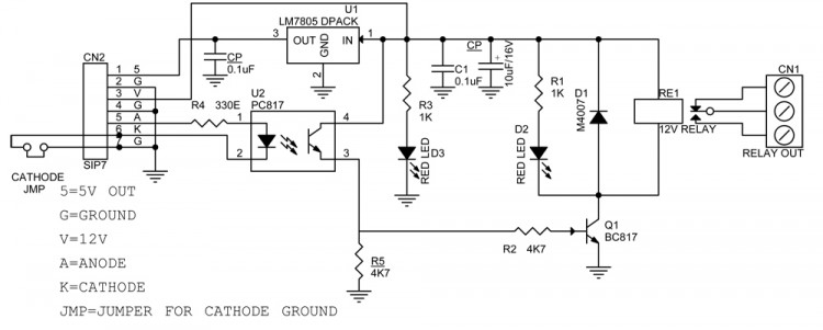
Schematic

SCHEMATIC1 : PAGE1

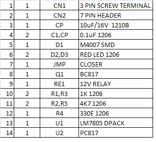
Parts List

BOM

Photos

I045B

I045C


Passive Infrared Detector Circuit

The infrared (IR) is invisible radiant energy, electromagnetic radiation that we cannot see with our eyes, but we can sometimes feel on our skin as heat. The infrared light falls just outside the visible spectrum, beyond the edge of what we can see as red. Most of the thermal radiation emitted by objects near room temperature is infrared.

The circuit uses a MCP6032 microchip operational amplifier. The MCP6032 operational amplifier (op amp) has a gain bandwidth of 10kHz with a low typical operating current of 900nA and an offset voltage that is less than 150uV. The MCP6032 uses Microchip’s advanced CMOS technology, which provides low bias current, high-speed operation, high open-loop gain and rail-to-rail input and output swing. The MCP6032 operates with a single supply voltage that can be as low as 1.8V, while drawing less than 1uA of quiescent current. The MCP6032 is available in standard 8-lead SOIC and MSOP packages. It also includes, a PID20 integrated circuit and a few electronic components. The size of the output signal of PID20 is determined by the task at pins 3 and 4. The output signal at pin 3 is compared with a reference voltage equal to half the supply voltage. The reference voltage is taken from the voltage divider R2-R3-R4-R5. When approaching an object warmer than the surrounding environment, or to remove an object colder than the environment, the output voltage increases. The variation of the sensor output will be compared, the IC2a and IC2b, located voltage of 0.5V under and over voltage reference respectively. Depending on the output, one of the comparators calculates and activates T1.

This basic circuit is used in night-vision devices with infrared illumination, which allows people or animals to be observed without the observer being detected. The infrared light is also used in industrial, scientific, and medical applications as well as in consumer devices.

Passive Infrared Detector Circuit – [Link]

Hacking a Blood Pressure Monitor

IMG_20150817_204925039

by Eduardo @ edusteinhorst.com:

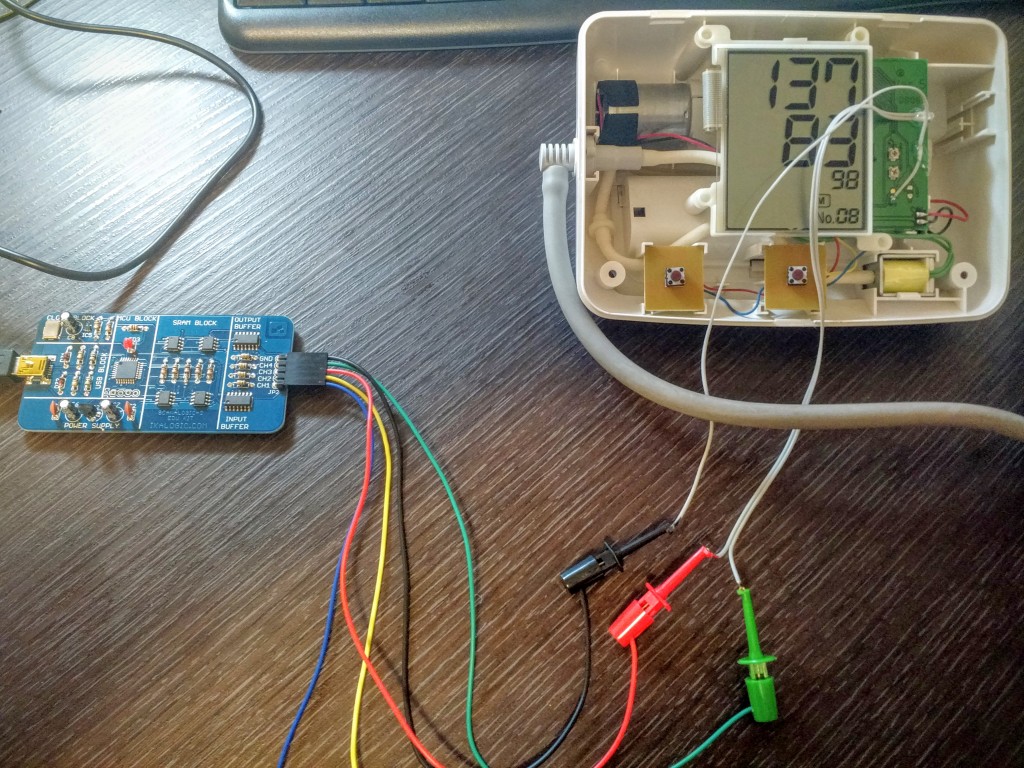
I’ve been meaning to hack my blood pressure monitor for a while, and I finally got around to doing it! So, the idea is to mod a regular electronic blood pressure monitor to make it wireless and connected to the Internet, much like iHealth BP5 or Withings’. That makes detecting trends in your blood pressure much easier, since you can chart the data and even correlate it with other health data, such as how much sleep you’ve been getting, your weight or your level of activity. The model I have is the EW3106 from Panasonic. It’s quite old but from what I’ve seen the design hasn’t changed much throughout the years.

Hacking a Blood Pressure Monitor – [Link]

EEVblog #806 – Siglent SDG2000X Arb Function Generator First Look

Dave takes a look at the new Siglent SDG2122X / SDG2042X Arb Generator and compares it to the Rigol DG4162 and the older Siglent SDG5082.
1.2GS/s arb gen for US$499! Including some performance measurements on the Tektronix MDO3000 spectrum analyser.

EEVblog #806 – Siglent SDG2000X Arb Function Generator First Look – [Link]

TOP PCB Companies