Fastest, highest-resolution DLP chipset for 3D print/lithography

151008edne-ti1

by Graham Prophet @ edn-europe.com:

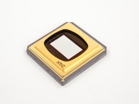
With its latest micro-mirror-based light-steering chip, Texas Instruments says, applications developers can innovate with more than 4 million micromirrors to enable high throughput digital imaging applications.

Presented as its highest speed and resolution chipset for 3D printing and lithography applications, TI’s DLP9000X digital micromirror device (DMD) and the DLPC910 controller, offers developers more than five times the speed at continuous streaming compared to the existing DLP9000 chipset.

The DLP9000X DMD delivers the highest streaming pixel speed in the TI DLP Products portfolio at over 60 gigabits per second.

Example application areas for the DLP9000X include 3D printing, direct imaging lithography, laser marking, LCD/OLED repair and computer-to-plate printers, as well as 3D machine vision and hyperspectral imaging.

Fastest, highest-resolution DLP chipset for 3D print/lithography – [Link]

Programmable Home Security Alarm System

In this project we design low cost high performance programmable home security system using few LDR’s as an input sensors. When above sensor(s) get triggered system may dial the user specified phone number (using build-in DTMF generator) and activate the high power audio alarm and lights. All the parameters of DTMF generator, audio alarm and light interface are programmed through the RS232 serial interface.

Current firmware of this system presents interactive control system through the RS232 interface. This control system consist with the menu driven configuration options, self tests, system report generators, etc.

This system also contain 5W (with 4Ω speaker) audio alarm with three selectable tone configurations, which include Police siren, Fire engine siren and Ambulance siren.

This system uses a Microchip’s PIC16F877A as a main controller, LM339 as sensor interface, UM3561 as a tone generator and μPC2002 as a speaker driver (audio amplifier). LM7805, LM7812 and LM317 voltage regulators are used to obtain +5V, +12V and +3V respectively.

This cheaper, self-made security measure is a DIYers dream, combining low cost parts with a sound piece of mind knowing you might have just installed the one thing that might thwart a burglar’s burgling. If the DIY route is not for you, then there are many low cost security options available.

All the project source codes, schematic diagrams and PCB patterns are available in “http://elect.wikispaces.com/Programmable+Home+Security+Alarm+System” with terms and conditions of GNU GPL and Creative Commons – Attribution-ShareAlike 3.0 Unported license

Programmable Home Security Alarm System – [Link]

Single Channel SMD Relay Driver

I040B

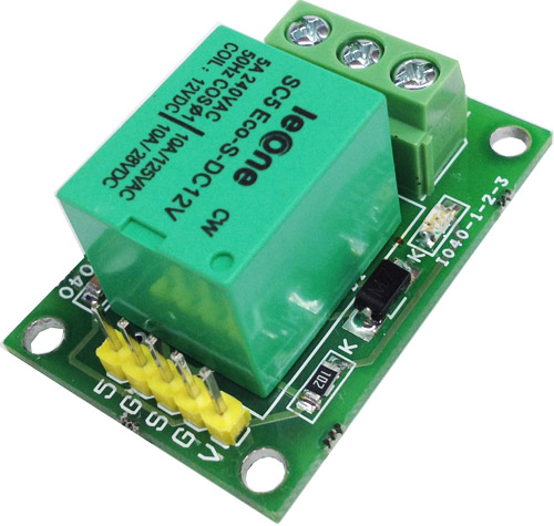
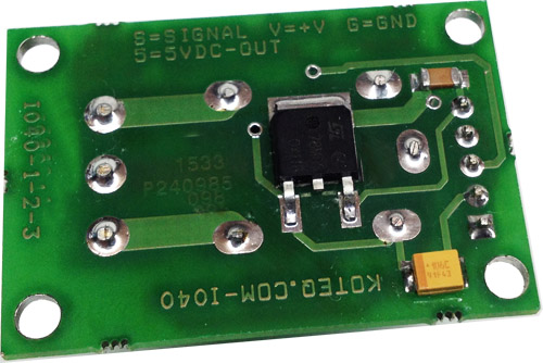
Single Channel Relay Board is a simple and convenient way to interface a relay for switching application in your project.

Specifications

  •     Input supply 12VDC @ 42 mA
  •     On Board 5V Regulator provides 5V output
  •     Output SPDT Relay
  •     Relay specification 5 A @ 230 VAC
  •     Trigger level 2 ~ 9 VDC
  •     Header connector for connecting power and trigger voltage
  •     Relay operations status LED
  •     Power LED
  •     Tiny Design
  •     Screw terminal connector for easy relay output connections

Single Channel SMD Relay Driver – [Link]

Single Channel SMD Relay Driver

I040B

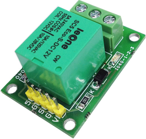
Single Channel Relay Board is a simple and convenient way to interface a relay for switching application in your project.

Specifications

  •     Input supply 12VDC @ 42 mA
  •     On Board 5V Regulator provides 5V output
  •     Output SPDT Relay
  •     Relay specification 5 A @ 230 VAC
  •     Trigger level 2 ~ 9 VDC
  •     Header connector for connecting power and trigger voltage
  •     Relay operations status LED
  •     Power LED
  •     Tiny Design
  •     Screw terminal connector for easy relay output connections

Schematic

SINGLE CHANNEL RELAY SCH

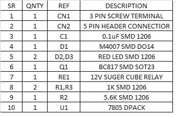
Parts List

BOM

Photos

I040D

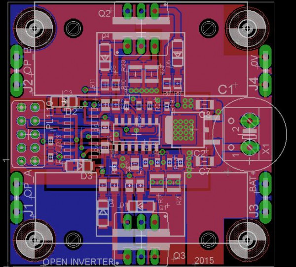
Open Inverter, an open source micro-solar inverter

open_inverter-600x543

Ken Boak has been working on an open source micro-solar inverter project:

We wanted to make a design that uses readily obtainable N-type FETS and an Arduino (more strictly a ATmega328P-PU on a breadboard) to generate the PWM signals and provide simple circuit protection, and load sensing. With the PWM signals generated in firmware it can easily be modified for 50Hz or 60Hz operation, either 115V or 230V operation and a wide range of battery input voltages.
We imagined that the final design could consist of an Arduino, an “Inverter Shield” containing FETs and driver ICs configued in a H-bridge and some voltage and current monitoring circuits. To make the inverter a 12V or 24V battery (or PV panel) and a 12V (or 24V) torroidal transformer would be added.

Open Inverter, an open source micro-solar inverter – [Link]

LiFePO4 charger

DSC01725

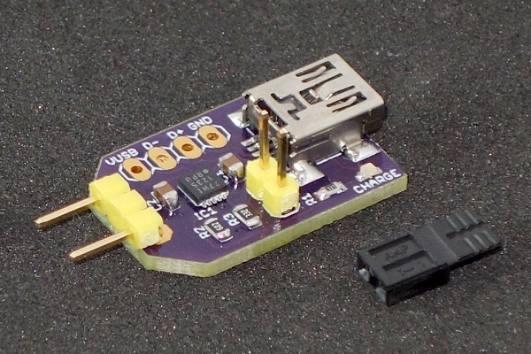
Markus Gritsch shared his LiFePO4 charger project in the forum:

Since I really like using LiFePO4 AA and AAA batteries in some of my projects, I finally gave in and built a dedicated charger for them.
Previously I used a lab power supply to mimic the constant current/constant voltage charging curve, which worked also fine. But after seeing Patrick Van Oosterwijck nifty LiFePO4wered/USB™, I thought it would be a bit more convenient to charge these batteries using USB.

LiFePO4 charger – [Link]

LTC4282 – High Current Hot Swap Controller with I2C Compatible Monitoring


4282

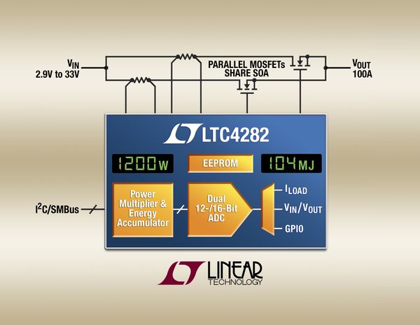
The LTC4282 is an energy monitoring Hot Swap controller with dual MOSFET drive to enable 100A and higher current board designs. The LTC4282 ensures safe board insertion and removal from live 2.9V to 33V backplanes by controlling external N­channel MOSFETs to gently power up capacitors, avoiding sparks, connector damage and system glitches. High current hot-pluggable boards utilize parallel MOSFETs to reduce voltage drop, but all of these MOSFETs require large safe operating area (SOA) to ride through overcurrent faults. By controlling two matching current limited paths, the LTC4282 halves each path’s SOA requirements, reducing MOSFET costs in high current applications (>50A). The LTC4282 provides a rugged, compact solution for hot plugging and monitoring, especially in high power circuit boards in servers, network routers and switches, and enterprise data storage systems.

LTC4282 – High Current Hot Swap Controller with I2C Compatible Monitoring – [Link]

Protection Methods for Automotive Electronics Circuits

littelfuse-automotive-aumov-pic2

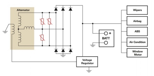
Jim Colby @ edn-europe.com discuss how to protect your circuits on automotive enviroment:

Along with the ever increasing drive for improved gas mileage, automobile manufacturers are striving to make their vehicles safer with each new design iteration. The safety features that are now available or standard on most vehicles, such as airbags, backup cameras, collision avoidance systems, and tire pressure sensors, have all drastically improved vehicle safety. The protections offered by these systems are obvious. But, there are also many unseen technologies that offer additional protection for the electronics systems in today’s vehicles.

As vehicles have become safer, so has the electronic circuitry that helps provide that safety. The advanced chipsets that are used in vehicles today are subjected to countless electrical hazards that are commonplace in the harsh automotive environment. Typical automotive electrical hazards or transients include lightning, electrostatic discharge (ESD) and switching loads in power electronics circuits.

Protection Methods for Automotive Electronics Circuits – [Link]

Arduino weather station with RF433 MHz modules

FODFQ7QIFCDG7VP.MEDIUM

by eliesalame @ instructables.com:

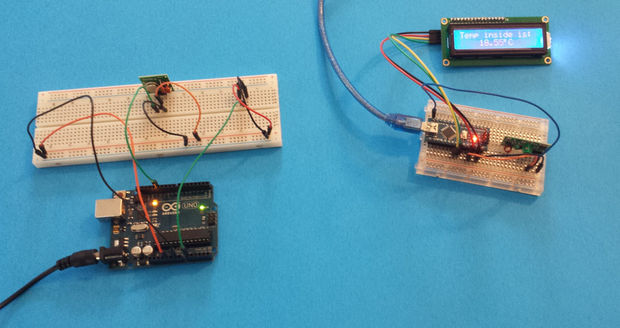
In this project I will show you how make two Arduinos talk to each other using RF frequency (wireless).

Now I will use the knowledge in all these project and improve on them by making one Arduino send data to another Arduino wirelessly using an RF433 module and displaying it on I2C serial LCD.

Arduino weather station with RF433 MHz modules – [Link]

Water Cooled Silicon Chips are reality

cooling-fpga2

Georgia Institute of Technology managed to cool FPGA trasistors using water, they announced:

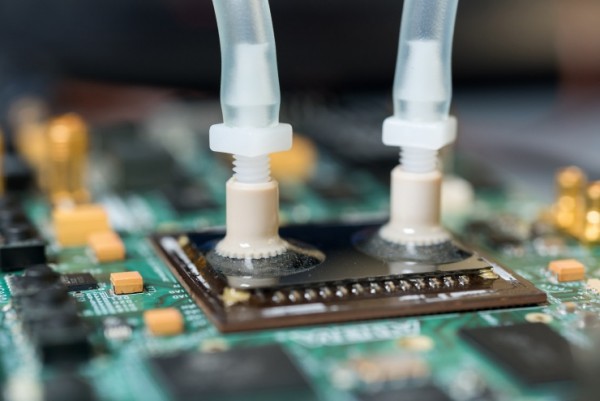
Using microfluidic passages cut directly into the backsides of production field-programmable gate array (FPGA) devices, Georgia Institute of Technology researchers are putting liquid cooling right where it’s needed the most – a few hundred microns away from where the transistors are operating.

Combined with connection technology that operates through structures in the cooling passages, the new technologies could allow development of denser and more powerful integrated electronic systems that would no longer require heat sinks or cooling fans on top of the integrated circuits. Working with popular 28-nanometer FPGA devices made by Altera Corp., the researchers have demonstrated a monolithically-cooled chip that can operate at temperatures more than 60 percent below those of similar air-cooled chips.

Water Cooled Silicon Chips are reality – [Link]

TOP PCB Companies