WireFrame FPGA Board , Breadboardable Xilinx XC3S250E Board

xilinx fpga board wire frame xc3s250e breadboard fpga (1)

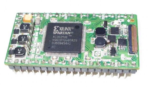
circuitvalley.com has build a small FPGA board based on Xilinx  XC3S250E :

I have built a little FPGA board Xilinx xc3s250e called WireFrame. the board is only 500mm x 25 mm in size and it is possible to put it breadboard. board has 32MByte SDRAM, 4MByte serial Flash for storage. total 3 2A max each Switching regulator for Vcc I/O 3.3V (adjustable trough regulator feed back resistors), VCCAUX 2.5 V and VCCINT 1.2v.

WireFrame FPGA Board , Breadboardable Xilinx XC3S250E Board – [Link]

Have you tried Serial to Ethernet communication?

obr1766_uvod

More than 50 developers tested Wiznet modules during Pizza workshops in Brno, Bratislava and Budapest.

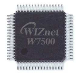
The main topic of Pizzaworkshop was Ethernet communication via Wiznet modules. Developers had a chance to test how fast and simple it is to connect the device to Ethernet and all of this was led by Joachim Wülbeck from Wiznet.Developers also tried working with EVB kits WIZ550S2E, as well as innovative WiZwiki-W7500. There were also answers for many questions about settings, programming, sending and receiving serial data via Ethernet, as well as troubleshooting the proposed applications.

Pictures will tell you more about how it looked like during the workshop… 🙂

Do you like our Pizzaworkshops?

Do not miss our next workshop in October with Lantronix. Sign up today. Number of seats is limited.

Have you tried Serial to Ethernet communication? – [Link]

DIY Infrared Remote Controls

ir_remote_control

by Jason Poel Smith @ makezine.com:

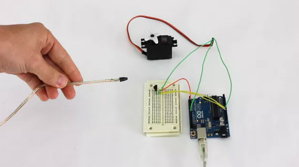
Halloween is the perfect opportunity to create fun special effects. When you want to be able to control props and effects remotely, one good option is to use an infrared remote control. In this project, I’ll show you some simple remote controlled effects that you can set up in your haunted house this year.

DIY Infrared Remote Controls – [Link]

Building the Colossus LED Display

by Adam Haile @ maniacallabs.com:

The 2014 NC Maker Faire was a huge turning point for Maniacal Labs. It was there that the idea for the AllPixel and what is now BiblioPixel got their start. It’s also where we showed off our first custom-built LED display, the 24×24 LPD8806 matrix. At nearly 24 inches square, and 1 pixel per inch, it was certainly impressive. But we left the Maker Faire with a desire to go bigger. Not just more pixels… but physically larger. Much larger. We call it “Colossus”.

Building the Colossus LED Display – [Link]

Arduino based MPPT solar charge controller

20150805_151734 copy

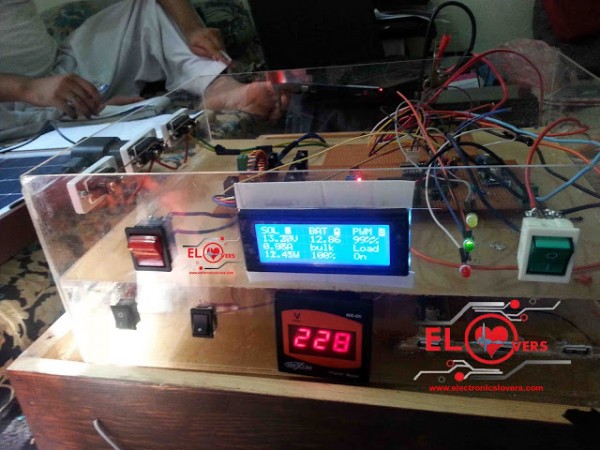
by Abid Jamal @ electronicslovers.com:

what is Mppt( Maximum power point tracking) ?
“we use MPPT algorithm to get the maximum available power from the Photovoltaic module under certain conditions”

How MPPT works ? Why 150W solar panel does not equal to 150 w?
For example you bought a new solar panel from the market which puts out 7 amps. under charge the setting of a battery is configured to 12 volts : 7 amps times 12 volts = 84w (P=V*I) You lost over 66 watts – but you paid for 150 watts. That 66 watts is not going anywhere, but it,s due to the poor match of the solar output current and battery voltage .

Arduino based MPPT solar charge controller – [Link]

Multi Channel Datalogger with OLED Display

coverImage

by Jed Hodson @ prototypingcorner.me:

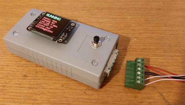
A 3 Channel Datalogger Powered by the LinkIt One. This device can log data from 2 Analog Inputs and 1 Digital Input / Output with PWM capabilities. The Device syncs time from GPS and makes use of the on-board battery to make it become even more portable. With an OLED Display to show system information and live data feed, along with the option to force an update all controlled via the 1 Button. The data file is stored on the LinkIt One’s internal storage and saved as a CSV file so it can easily be read by a text editor or a more powerful program (such as Excel). Fully Customizable and with room to expand all via the software that makes it run.

Multi Channel Datalogger with OLED Display – [Link]

Teardown & Repair of a Stanford Research PS350 5000V, 25W High Voltage Power Supply

In this episode Shahriar repairs a Stanford Research Systems Model PS350 5000V-25W High Voltage Power Supply. The unit continuously displays 2.5kV without the output being enabled and produces no output voltage. Verification of power supply voltages reveals the issue is linked to a disconnected 15V voltage regulator IC. After the repair, the output voltage is verified with both positive and negative outputs. The principle operation of the instrument as well as the Cockroft-Walton high voltage generator is reviewed.

Teardown & Repair of a Stanford Research PS350 5000V, 25W High Voltage Power Supply – [Link]

TOP PCB Companies