Make a Weather Station With a Raspberry Pi 2

raspberry-pi-weather-station-00

Jeremy Morgan @ jeremymorgan.com writes:

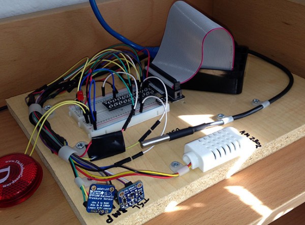
Today I’m going to show you how to make sort of a mini weather station with a Raspberry Pi. This is an ongoing project of mine that I’ve been tinkering with so I’ll share my learnings with you. It started with a project I wrote about last month, and is an improvement on it.

A core part of the “Internet of Things” movement is the idea of devices that gather data and send it to the Internet. That data is then acted on or observed for later. It’s a simple concept and has been going on for a while but lately it’s been getting cheaper and easier to do. This project is a great example of that.

Make a Weather Station With a Raspberry Pi 2 – [Link]

PCB stencil jig

PCB_stencil_jig

Gonazar’s PCB stencil jig:

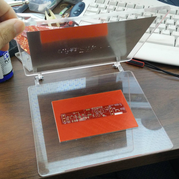
My solution to making a PCB stencil jig.
I need this to do a run of ~30 small boards I got from DirtyPCB who also provided me with the stencil. However, I know that I’m going to be making more later with a new revision so I wanted a jig that I could later reuse with a new design.
One of the challenges of making a pcb jig is alignment and finding something to lie next to the pcb so the stencil doesn’t bow/bend from unsupported areas.
So my design uses two 1/8″ thick acrylic frames on a hinge. The top frame has a large opening to work with the stencil and the bottom frame has a fixed rectangular hole. This hole is for placing a 3D printed jig that perfectly matches the PCB shape and thickness. It’s also exactly the dimension of a 8.5″x11″ cut into 8 pieces. This way I can lock in my PCB and align my stencil, then adjust the height by shimming it with pieces of paper underneath.

PCB stencil jig – [Link]

Can a current flow even up the hill?

obr1755_uvod

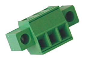
Of course it can, even apeak. So if you connect leads from the bottom side via a PCB connector, you don´t have to worry about the current…

Should you however be afraid of accidental fall off of the connector (it will certainly hold on if there are no vibrations, shocks or unpredictable tension to leads), then for your peace of mind we recommend you to use connectors that can be secured by a screw.

Naturally, devices exposed to vibrations are much more frequent (for example with a motor) or even devices which are often subjeted to transport – for all such cases a connector with a flange (and integrated screw) finds its place.

Such solution is also offered by a well-known producer of terminal blocks – EUROCLAMP. For example for currents up to 8 Amps and voltages to 160V, these novelties from our stock are suitable:

  • SH04-3,5-K (4-pole plug-in connector for cable, with a 3.5 mm pitch, with a flange and screw)
  • PV04-3,5-V-K (a mating piece to SH04-3,5 for a PCB with a flange and screw) For a real certain feeling, this component can be screwed to a PCB by a self tapping screw ( ISO1481-ST 2,2×4,5(6,5)C screw, not included)

A screw also prevents accidental disconnection (it´s only possible with a screwdriver). In extreme case, the screws can be replaced by security head screws… (but this perhaps no – if you deal with a critical device – then use some more efficient precautions).

Detailed information can be found in the SHxx-3,5-K and PVxx-3,5-V-K datasheets.


Can a current flow even up the hill? – [Link]

High Speed Ecosystem Support and Calamity Monitoring System

The innovation of equipment for calamity detection and monitoring are quite rampant. It is because of consecutive aggression of storms and earthquakes in different parts of the world. As to observe the different scenarios, these are not merely natural causes, there are some or most of it is manmade. A good example of it is a storm, which is the combination of hot and cold air. These hot and cold airs are natural but the rapid change of air temperature is not natural. Aside from air, water is another major contributor to global warming. Abnormalities that happened to the body of water affect the entire ecosystem, which also affect both living and nonliving things. With such cases, the environment needs care from people. This simple design of ecosystem support and calamity detection will be a great help in protecting the nature and preventing major disasters from occurring. It features two sensing parameters such as pressure and pH level. It has Fast-mode Plus (Fm+) capability on its buses, which can be configured to communicate up to 64 slaves in one serial sequence with no intervention from the CPU. It can communicate remotely and locally where GSM is unavailable.

The design is comprised of SST89E52RC-33-C-PIE legacy microcontroller as the main processor of the device. It is interfaced with the PCA9661 parallel bus to 1 channel Fm+ I2C-bus controller with 74HC237D as the decoder. This interface provides the ports for the sensors, which it communicates at high speed data transfer. The two sensor attached to the I2C-bus controller are SEN-10972 pH sensor and MPL115A1T1 miniature I2C digital barometer. The SEN-10972 pH sensor is used to monitor the pH level of water in which a change of pH level signifies abnormalities or some toxic chemicals that are present in water. The MPL115A1T1 barometer is used to monitor the possibilities of a developing tropical storm or typhoon. The GSM module is for remote data communication with central station or any portable device that is GSM communication capable. In case of a local monitoring and GSM signal dead zone, a built in RF transmitter will trigger to transmit data to any portable device or stations within the range of RF transmission.

The innovation of this device will surely help both the people and environment. It can result to a lesser number of casualties and agricultural damages. It can help the development of municipalities, cities, and/or even nations since it saves a lot of investments and other types of income. This design can be integrated to several developments that can provide more efficient and useful technology instrument for the people and the environment.

High Speed Ecosystem Support and Calamity Monitoring System – [Link]

18 PIN PIC Development Board

18PIN-PIC-Development-Board-PIC

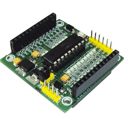
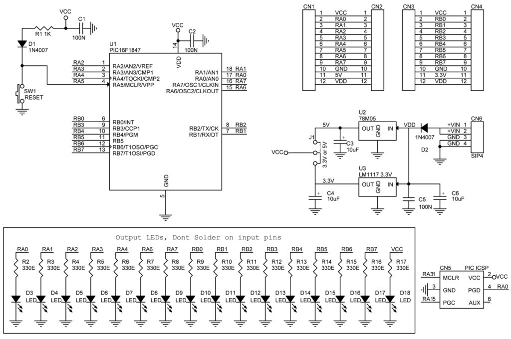
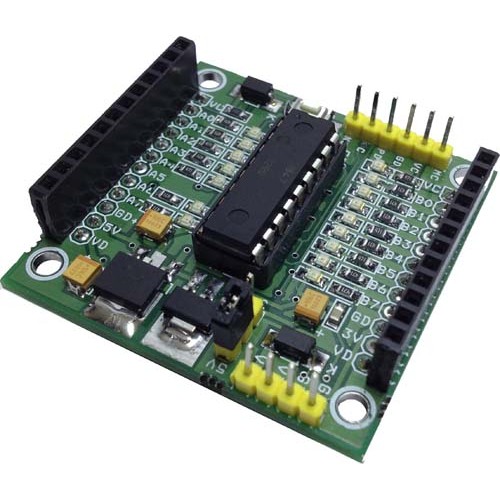
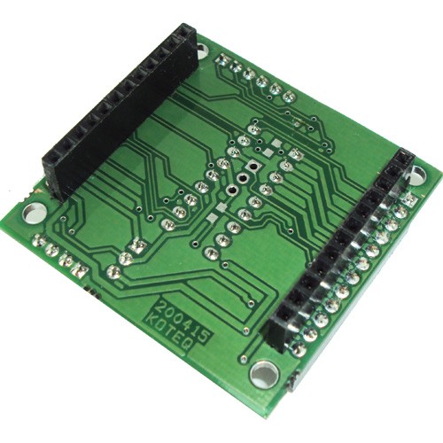
The PIC 18 PIN (DIP) Development / Evaluations Board demonstrates the capabilities of Microchip’s 8-bit microcontrollers, specifically, 18 Pin PIC16F1847. It can be used as a standalone demonstration board with a programmed part. With this board you can develop and prototype with all Microchip’s 18 PIN PIC microcontrollers. The board has a Reset switch and status LEDs. On board 3.3 V and 5V DC regulators allows using 3V and 5V PICs, This board support both 3.3V low power and normal 5V operation. All I/O Pins out with 2 x female headers

Development Board Features:

  • 16 I/O Ports
  • Onboard 5V and 3.3V Supply
  • 3.3V or 5V Supply selection by jumper
  • Dual line I/O
  • On board Power Indication
  • On-board ICSP Port (PICKIT2 Standard Programming Port)
  • Well labeled legends
  • All outputs has provision for LEDs for output indication
  • Replaceable PIC Microcontroller,
  • Crystal and capacitor mounting under the PCB

18 PIN PIC Development Board – [Link]

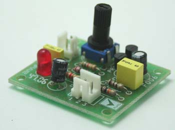
18 PIN PIC Development Board

18PIN PIC Development Board PIC

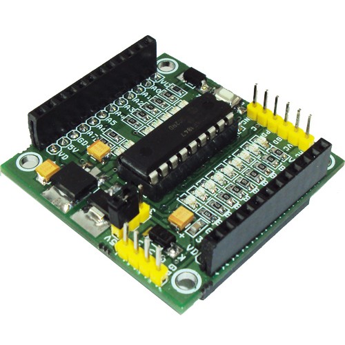
The PIC 18 PIN (DIP) Development / Evaluations Board demonstrates the capabilities of Microchip’s 8-bit microcontrollers, specifically, 18 Pin PIC16F1847. It can be used as a standalone demonstration board with a programmed part. With this board you can develop and prototype with all Microchip’s 18 PIN PIC microcontrollers. The board has a Reset switch and status LEDs. On board 3.3 V and 5V DC regulators allows using 3V and 5V PICs, This board support both 3.3V low power and normal 5V operation. All I/O Pins out with 2xfemale headers

Development Board Features:

  •     16 I/O Ports
  •     Onboard 5V and 3.3V Supply
  •     3.3V or 5V Supply selection by jumper
  •     Dual line I/O
  •     On board Power Indication
  •     On-board ICSP Port (PICKIT2 Standard Programming Port)
  •     Well labeled legends
  •     All outputs has provision for LEDs for output indication
  •     Replaceable PIC Microcontroller,
  •     Crystal and capacitor mounting under the PCB

PIC16F1847 Micro-Controller Specifications:

  • Enhanced Mid-range Core with 49 Instruction, 16 Stack Levels
  • Flash Program Memory with self read/write capability
  • Internal 32MHz oscillator
  • Integrated Capacitive mTouch Sensing Module
  • Data Signal Modulator Module
  • MI2C, SPI, EUSART w/auto baud
  • 2 ECCP & 2 CCP (Enhanced/Capture Compare PWM)
  • Comparators with selectable Voltage Reference
  • 12 Channel 10b ADC with Voltage Reference
  • 25mA Source/Sink current I/O
  • Four 8-bit Timers (TMR0/TMR2/TMR4/TMR6)
  • One 16-bit Timer (TMR1)
  • Extended Watchdog Timer (EWDT)
  • Enhanced Power-On/Off-Reset
  • Brown-Out Reset (BOR)
  • In Circuit Serial Programming (ICSP)
  • On Board In-Circuit Debug
  • Wide Operating Voltage (1.8V – 5.5V)
  • Low Power PIC16LF182x/4x variants (1.8V – 3.6V)
  • Standby Current (PIC16LF1847): 30 nA @ 1.8V, typical
  • Program Memory Type Flash
  • Program Memory (KB) 14
  • CPU Speed (MIPS) 8
  • RAM Bytes 1,024
  • Data EEPROM (bytes) 256
  • Digital Communication Peripherals 1-UART, 1-A/E/USART, 2-SPI, 2-I2C2-MSSP(SPI/I2C)
  • Capture/Compare/PWM Peripherals 2 CCP, 2 ECCP
  • Timers’ 4 x 8-bit, 1 x 16-bit
  • ADC 12 ch, 10-bit
  • Comparators 2
  • Temperature Range (C) -40 to 125
  • Operating Voltage Range (V)1.8 to 5.5
  • Pin Count 18
  • XLP Yes
  • Cap Touch Channels 12

Schematic

SCHEMATIC1 : PAGE1


Pinout

pinout

Photos

18PIN PIC Development Board PIC2

18PIN PIC Development Board PIC3


Arduino – How to use a Force Sensitive Resistor

FIE2TLMIEV84MV8.MEDIUM

by codebender_cc @ instructables.com:

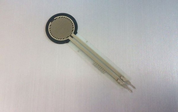
In this tutorial you will learn how to use an FSR – Force Sensitive Resistor with Arduino to fade an LED. This sensor is a variable resistor just like a photocell or flex sensor. The resistance changes by applying pressure on it.

Arduino – How to use a Force Sensitive Resistor – [Link]

Laser Diode Driver

LASER-DIODE-DRIVER-PIC

Laser Diode Driver project will help you safely drive (constant current) a 3 mW visible Laser Diode for your application.

  • Input supply – 2.5 to 6 VDC
  • Onboard preset to adjust the current flow to the Laser Diode
  • Power-On LED indicator
  • Header connector for easy input supply and LASER DIODE module connection
  • Laser diode is not included
  • Circuit is designed around Sanyo DL3148-025 LASER DIODE
  • PCB dimensions 37 mm x 42 mm

Laser Diode Driver – [Link]

8V97051 Low Power Wideband Fractional RF Synthesizer

This design features a low power wideband RF synthesizer that is used in GSM receiver cards. It has dual differential and open drain outputs with frequency range of 34.375MHz to 4400MHz(in continuous range). The logic compatibility is 1.8V while the system is running on a single 3.3V supply. It has -143dBc/Hz Phase Noise (PN) performance at 1MHz Offset for every 1.1GHz output. It is also capable of mute function at RF_OUT that is accessible via mute pin or SPI command. It is low power with only 380mW average power consumption while RF_OUTB is not in used.

The design is comprised of 3 major parts. The first part consists of IDT8V97051NLGi wideband RF synthesizer/PLL supports the output frequencies with Voltage Controlled Oscillator (VCO). The temperature compensated crystal oscillator close to the RF input helps in the precision of signal while the other parts are filters that are used in various purposes like minimizing undesired noise. The second part consists of the USB 2.0 high speed to UART/FIFO IC that is used for system interface while the I2C-bus to SPI bridge IC controls the sequences, protocol, and timing of the signal. The last part is power supply management of the system in which it is provided with RC filters in every line to ensure minimal noise are included in the supply.

The design is applicable in multi-carrier, multi-mode Frequency Division Duplexing (FDD) and Time Division Duplexing (TDD) base station radio card. It optimizes multi-service base stations during its service as a local oscillator that generates a large variety of frequencies to mixers while maintaining excellent PN.

8V97051 Low Power Wideband Fractional RF Synthesizer – [Link]


TOP PCB Companies