Smart Garden

FP41D94IETSNTGL.MEDIUM

by FABLAB Dhahran @ instructables.com:

In this project we will design and program a smart garden watering system. This system will use Arduino UNO and a moisture sensor to measure the volumetric water content in soil. It will also have a light (photocell) sensor to detect when the plant should get sunlight. So, when the soil is dry a red LED will light up, when it’s wet a blue LED will light up, and when the plant needs a light a white LED will blink. You will need basic 2D-designing skills and CNC machine to design and build our own planter box. Alternatively, you can just use a normal jar. Also, you can make your planter box using acrylic and cut it by a laser cutting machine.

Smart Garden – [Link]

Industruino – Arduino compatible industrial controller

ir_attachment_203

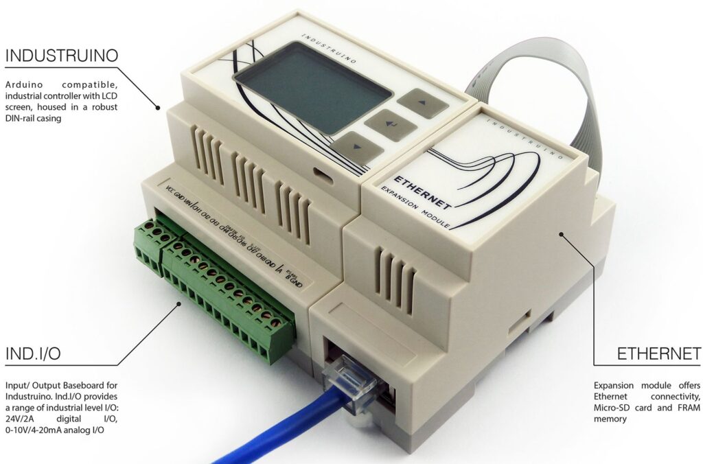
Industruino is a fully featured Arduino Leonardo compatible board housed in a DIN-rail mountable case + prototyping area + onboard LCD + membrane panel. With this product you will be able to permanently install your Arduino application in no-time.

Whether you use it for automation projects, data loggers or an interactive art installation, Industruino offers you ruggedness, plenty of features and low cost.

Industruino – Arduino compatible industrial controller – [Link]

AC energy metering board using an Atmel 90E24 energy metering chip

acpowermonitor-600x450

Steve Rodgers writes:

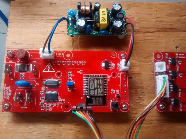
Here’s my latest project. Its an AC energy metering board using an Atmel 90E24 energy metering chip. The board can either take an ESP8266-12 and run a native C application, or the ESP8266-12 can be omitted, and an external microcontroller can be used to talk to the Atmel 90E24 energy metering chip. I have firmware to support both the AVR and the ESP8266. I built a really nice energy monitoring box using the AVR and a 12864 display.

AC energy metering board using an Atmel 90E24 energy metering chip – [Link]

Surface-mount device prototyping in education

smd_parts

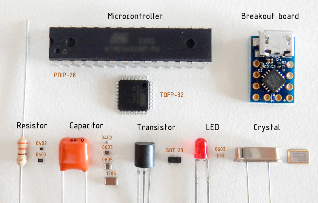
In this article Vassilis K. Papanikolaou explains how SMD prototyping practice can be used in learning environments using simple and wide available tools and equipment:

A feasibility study is herein attempted, towards the adaptation of modern surface-mount device (SMD) prototyping practice to learning environments. This necessity emerges not only from the profound advantages of the above technology (e.g. component size, availability, low cost etc.) but also from the fact that contemporary designs often require special board layout considerations, which may be incompatible with through-hole components. In addition, the long process between prototyping and product finalization can be greatly shortened. Nevertheless, the employment of surface-mount techniques in education may be discouraged by both the unappealing part sizes (i.e. handling difficulty) and the excessive cost of commercial supporting equipment. The main objective of this study is to suggest practical and low-cost solutions for all different SMD prototyping/manufacturing stages, which can demystify and render this procedure welcome and easily applicable in laboratory classes.

Surface-mount device prototyping in education – [Link]

MC34VR500V1ES Multi-Output DC/DC Regulator

The circuit in this reference design features the capability of MC34VR500V1ES to supply multiple DC voltage outputs. This device is designed to support the LS1/T1 family of communication processors, which require efficient and precise level of voltage supplies. With its four switching and five linear regulators, the MC34VR500V1ES can supply power to the whole system, e.g., the processor, memory, system peripherals.

The MC34VR500V1ES device runs with a supply voltage ranging from 2.8V to 4.5V. It can provide nine outputs. Four of these outputs (SW1-4) are buck regulators while the rest (LDO1-5) are general purpose LDOs. Each one of the buck regulator is capable of operating in Pulse Frequency Modulation (PFM), Auto Pulse Skip (APS), and Pulse Width Modulation (PWM) switching modes. These buck regulators also have a current limit feature that generates a fault interrupt whenever there is an overcurrent condition. The SW1 output is capable of providing 0.625-1.875V/4.5A supply while SW2 and SW3 can provide 0.625-1.975V/2A and 0.625-1.975V/2.5A, respectively. The SW1, SW2 and SW3 voltages can be varied with a step size of 25mV. The SW4 output is half of the voltage output of SW3. The general output LDOs can output voltages ranging from 1.8-3.3V with a step size of 100mV except for LDO1 which can only give 0.8-1.55V output with 50mV step size. The LDO1 output can provide current up to 250mA, while LDO2 and LDO4 can output up to 100mA only. The LDO5 output can provide 200mA of current while LDO3 can output up to 350mA. Aside from these nine outputs, the MC34VR500V1ES also have a REFOUT output dedicated for DDR memory reference voltage. The voltage of this REFOUT output is usually half of the SW3 output and can only provide up to 10mA of current. The MC34VR500V1ES outputs can be changed by programming it via the I2C interface.

The operation of the MC34VR500V1ES can be reduced to four states, or modes: ON, OFF, Sleep, and Standby. For the device to turn ON, the input voltage must surpass a voltage threshold of 3.1V, the EN pin must be high, and PORB is de-asserted. The 34VR500 enters the OFF mode when the EN pin is low or there is a thermal shutdown event that forces the device into the OFF mode. Standby mode is usually entered when the STBY pin is asserted for low-power mode of operation. The device only goes into sleep mode if the EN pin is de-asserted. To exit sleep mode, assert the EN pin.

MC34VR500V1ES Multi-Output DC/DC Regulator – [Link]

DIY Miniature and Wearable Electronics

hwey7rvrq5lb3xtytzjx

MiniWear – DIY Miniature And Wearable Modules That Can Be Worn Anywhere On The Body. James Cannan writes:

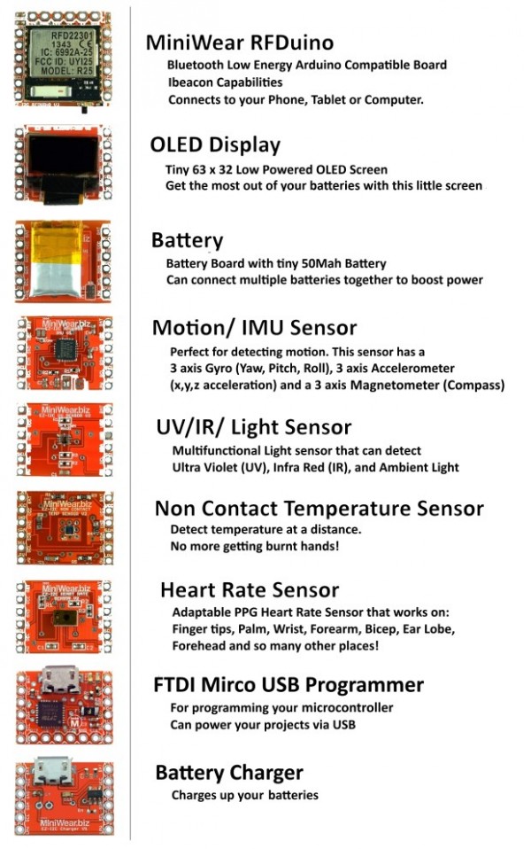
We love electronics, especially Wearables, and that is why we have made super cool modules that include heart rate detection, movement, non contact temperature sensing, and ultraviolet (UV), infra-red (IR), and light sensing technology. We are also one of the first in the world to have combined our modules with a variety of open source 3d printed cases, which will take your projects to a whole new level!

DIY Miniature and Wearable Electronics – [Link]

NE555 timer sparks low-cost voltage-to-frequency converter

voltage_to_frequency

by Gyula Dioszegi @ edn.com:

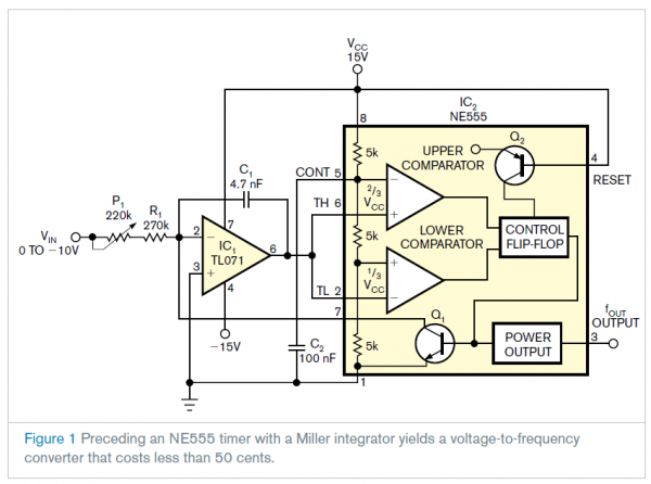
In 1971, Signetics—later Philips—introduced the NE555 timer, and manufacturers are still producing more than 1 billion of them a year. By adding a few components to the NE555, you can build a simple voltage-to-frequency converter for less than 50 cents. The circuit contains a Miller integrator based on a TL071 along with an NE555 timer (Figure 1). The input voltage in this application ranges from 0 to –10V, yielding an output-frequency range of 0 to 1000 Hz. The current of C1 is the function of input voltage: IC=–VIN/(P1+R1).

NE555 timer sparks low-cost voltage-to-frequency converter – [Link]

JFET Moving Coil (MC) Pre-Preamp Kit

OLYMPUS DIGITAL CAMERA

by Mark Houston @ diyaudioprojects.com:

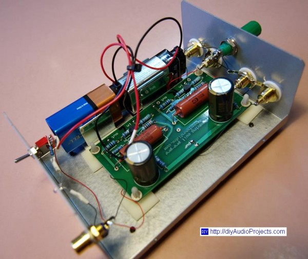
I received the Boozhound Labs JFET Moving Coil (MC) Pre-Preamp Kit a while back and I promptly assembled the small circuit board. I’m a sucker for a simple kit and a hot iron. That is where it all stopped. The circuit board remained complete and laying about for a few years. Recently I required another MC stage because the tube moving-magnet (MM) preamp I had just completed did not work all that well with the Jean Hiraga MC stage I had been using for years. It appeared the Hiraga had too much output and was over-driving the tube stage. So I needed another MC stage.

JFET Moving Coil (MC) Pre-Preamp Kit – [Link]

Miniscope v2f

assembled_pcb

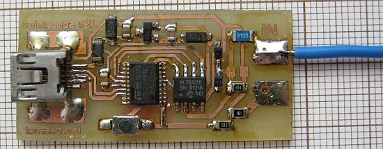
Here is another variant (after miniscope v2a, b, c, d, e) of simple PC/USB oscilloscope/recorder:

http://tomeko.net/miniscope_v2f/

It extends miniscope v2e with PGA (MCP6S21) offering same sampling frequency (480 ksps, 8 bit real time streaming to PC allowing continuous recording up to 512M samples) but 8 gain ranges and high input impedance. Estimated price is $6 – $7 if using homemade PCB (single sided, 1.35 sq inches).

Miniscope v2f – [Link]

WiFi-based Weather Forecast and Clock

1

by soniktech.com:

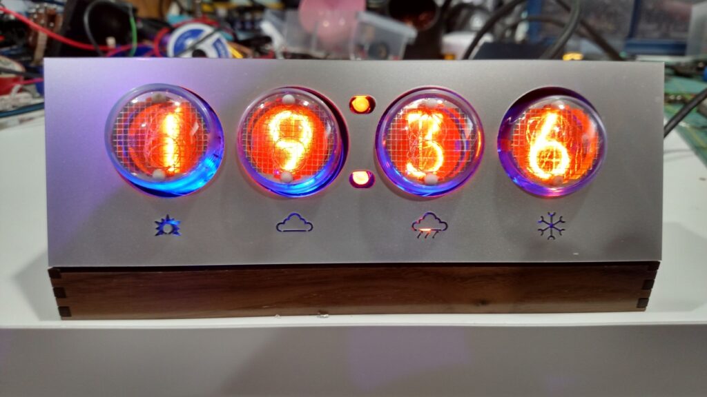
This project is a stopgap on my way to building a ground-up “Internet of Things” base design around the ESP8266 SoC WiFi solution. I started by taking a few nixie tubes I’ve had lying around from a past project, and connecting them to a Nixie Power supply I found on ebay. After making sure they lit up, I wired the Nixies up to a HV5622 chip (which anyone who makes Nixie clocks should really consider for their designs).

WiFi-based Weather Forecast and Clock – [Link]

TOP PCB Companies